


Reference Design
Dimmable Light Ballast with Power Factor Correction, Rev. 1
24 Freescale Semiconductor
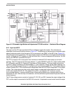
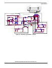
the PFC switch in hysteresis current control mode or output is used for switch off PWM1 in DCM. Than
PWM1 signal is used directly for switching the PFC switch transistor.
3.3.3 Protection Features
During the startup phase and run phase, some erroneous states can occur. When the DC-bus voltage
does not reach the required value or is out of limits then a fault signal is generated. The DC-bus voltage
is also checked against limits in run mode. If any of the previously mentioned faults occurs, all modules
are disabled, lamps go out, and the fault diode blinks.
3.4 Software Specification
The software is written in C. The software specifications are listed in Table 3-2. A useful feature of this
application is the ability to debug software via the MON08 CYCLONE debug tool connected to JP1 header
connector. The Real-Time Debugger from Metrowerks can be used as a debug tool.
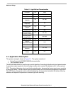
Table 3-2. Software Specification
Control Algorithm
Dithering control
Current loop control
Voltage loop control
Target Processor MC68HC908LB8
Language C with some arithmetical functions in assembler
Compiler Metrowerks ANSI-C/C++ Compiler for HC08
MCU Oscillator Frequency 16 MHz (with default software setting)
MCU Bus Frequency 4 MHz (with default software setting)
Targeted Hardware Dimmable Light Ballast With PFC Demo Board
A detailed description of how to set Debugger for commutation with MON08 CYCLONE is given in
Reference [
2]. For safe debugging it is recommended use an opto-isolation board connected between the
MON08 CYCLONE and the Light Ballast Demo Board. The Opto-isolation Board user manual can be
found in Reference [
3].
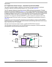
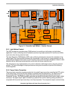
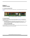
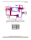
3.5 Hardware Specification
The other system specifications are determined by the target hardware and lamp characteristics. The
board and its connections are shown in
Chapter 4 Hardware Design.
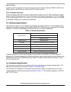
This hardware set is designed for fluorescent lamp and mains voltage. The specifications for a high
voltage hardware and fluorescent lamp set are listed in
Table 3-1. The hardware operates on 230 VAC
and 110 VAC mains.