


FILTER RECTIFIER
PFC
POWER
SUPPLY
DRIVER
HALF BRIDGE
RESONANT
CIRCUIT
DIFFERENTIAL
VOLTAGE
FLUORESCENT LAMPS
DRIVER
DC-BUS
HIGH
RESOLUTION
PWM
PWM
GENERATION
USER INTERFACE
MONITOR
MODE
LUMINANCE
LEVEL
PI
REGULATOR
BRIGHTNESS
LINEARIZATION
DC-
BUS VOLTAGE
ZERO
CROSSING
TUBE 2 CURRENT
TUBE
1
CURRENT
MC68HC908LB8
ACTUAL CURRENT
i
req
f
HRP
U
REQ
e
-
i
act
MAINS
CURRENT
PROCESSING
CONTROL BOARD
FILTER
-
+
sineGain
PWM
PWM
e
e
PI
REGULATOR
-
FILTER RECTIFIER
PFC
POWER
SUPPLY
DRIVER
HALF BRIDGE
RESONANT
CIRCUIT
DIFFERENTIAL
VOLTAGE
FILTER RECTIFIER
PFC
POWER
SUPPLY
DRIVER
HALF BRIDGE
RESONANT
CIRCUIT
DIFFERENTIAL
VOLTAGE
FLUORESCENT LAMPS
DRIVER
DC-BUS
HIGH
RESOLUTION
PWM
PWM
GENERATION
USER INTERFACE
MONITOR
MODE
LUMINANCE
LEVEL
PI
REGULATOR
BRIGHTNESS
LINEARIZATION
DC-
BUS VOLTAGE
ZERO
CROSSING
TUBE 2 CURRENT
TUBE
1
CURRENT
MC68HC908LB8
ACTUAL CURRENT
i
req
f
HRP
U
REQ
e
-
i
act
MAINS
CURRENT
PROCESSING
CONTROL BOARD
FILTER
-
+
sineGain
PWM
PWM
e
e
PI
REGULATOR
-
Application Description
Dimmable Light Ballast with Power Factor Correction, Rev. 1
Freescale Semiconductor 23
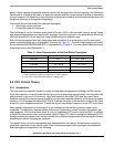
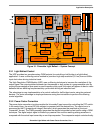
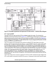
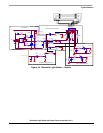
Figure 3-1. Dimmable Light Ballast — System Concept
3.3.1 Light Ballast Control
The HRP provides two complementary PWM outputs for controlling a half-bridge in a light ballast
application. It uses a dithering control method to provide a high step resolution (3.9 ns) from an 8
MHz
input clock when driving inductive loads.
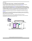
The High Resolution PWM Module (HRP) uses a dithering technique to increase the resolution of the
output signal.The output switches between two frequencies or duty cycles at a programmable rate. By
varying the percentage of time spent on each frequency/duty cycle, the output will appear to be at a value
between the two dithering frequencies/duty cycles when driving an inductive load.
The advantage is easy implementation of a control method for half-bridge inverter using few external
devices. The main advantage is simple performance using few instructions to perform the dithering
control algorithm.
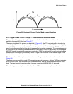
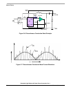
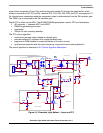
3.3.2 Power Factor Correction
The power factor correction circuitry provides the “sinusoidal” input current by controlling the PFC switch.
In the control loop, the actual DC-bus voltage is compared with the desired one. The control error is
processed by the PI (proportional-integral) controller, which generates the amplitude of the input
“sinusoidal” current. The PWM generator generates the desired sinusoidal current profile using a PWM
technique. The digital output signal is filtered by a passive filter and the resulting analog waveform is
compared with the actual input current by an on-chip comparator. The comparator output controls directly