


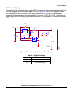

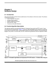

Software Implementation
Dimmable Light Ballast with Power Factor Correction, Rev. 1
Freescale Semiconductor 41
– PWM clock frequency set to BUSCLK by prescaler bits PRSC0 and PRSC1
• DISMAP is a write-once register which controls the PWM pins to be disabled if an external fault
occurs. When this register is written for the first time, it cannot be rewritten unless a reset occurs.
PWM0 is not disabled when an external fault appears. PWM1 is disabled if an external fault
appears.
• The FCR register controls the fault protection circuitry. A fault does not cause a CPU interrupt in
hysteresis current control mode. The fault protection circuitry operates in automatic mode for DCM
HW variation. In hysteresis current control mode operates in manual mode.
The PWM frequency is affected by the setup of the internal bus frequency, PWM modulus registers
PMODH, PMODL, and the prescaler value in the PRSC0 and PRSC1 registers. Consequently, the PWM
frequency is given by the equation:
PWM Frequency
BusFrequency
PMOD PRSC[0:1]×
--------------------------------------------------
Hz; Hz, -, -[]=
(EQ 5-6)
According to the setting, the PWM frequency is 40 kHz.
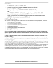
5.3.1.2 HRP Setup
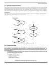
The HRP provides two complementary outputs for controlling a half-bridge in a light ballast application. It
uses a dithering control method to provide a high step resolution (< 4 ns) from an 8 MHz input clock when
driving inductive loads.
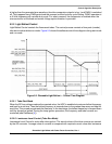
For the to operate properly, the HRP registers must be set correctly. The HRP works in variable frequency
mode with 50% duty cycle. The output frequency varies from 40 kHz up to 120 kHz, depending on the
level of dimming required. The MCU BUSCLKX2 is 8 MHz. The transistors controlling the lamp require a
deadtime of 1 µs. The deadtime must be set by software.
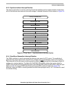
Four steps are required to configure the HRP:
1. Set the dithering timebase to the appropriate value
2. Set the deadtime to the appropriate value
3. Set HRPPERH:HRPPERL to select the desired frequency
4. Select variable frequency mode and enable the module
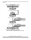
Detailed description follows:
1. Set the dithering timebase to appropriate value:
The dithering timebase is determined by HRPTBH:HRPTBL registers. It should be calculated
according to the condition:
Dithering timebase (seconds) >= (1/max ballast frequency)
HRPTBH:HRPTBL = (1/max ballast frequency) * BUSCLKX2
In this case, dithering timebase = 1/120 kHz = 8.33 µs
For BUSCLKX2 = 8 Mhz, the HRPTBH:HRPTBL = $0054
2. Set deadtime to appropriate value:
The deadtime is defined by HRPDT register.
The transistors used in the ballast require 1 µs of deadtime to prevent both being on at the same
time.
HRPDT register = required deadtime / (1 /BUSCLKX2)