


Software Design
Dimmable Light Ballast with Power Factor Correction, Rev. 1
36 Freescale Semiconductor
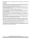
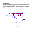
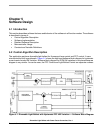
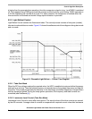
5.2.1 Power Factor Correction Control
PFC control consists of DC-bus voltage control using the PI controller, phase shift synchronization,
reference sine wave generation and generation of output PFC control signals. It also includes the
trimming of the internal oscillator frequency according to the frequency of the mains provided.
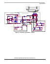
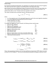
5.2.1.1 DC-bus Voltage Control
The actual value of the DC-bus voltage is sensed by the AD converter. This value is compared with the
required DC-bus value. The regulation error is then the input value for the PI regulator. The output value
from the PI regulator is the reference sine wave gain. The PWM module generates a reference sine wave
with calculated amplitude. The filtered reference sine wave is compared with the actual current using the
on-chip comparator. For the hysteresis current control mode HW variation, the output from the
comparator is the switching signal for the PFC MOSFET transistor. For the discontinuous conduction
mode HW variation, the output comparator is connected to the PWM fault pin. The PWM1 signal is directly
used for switching the PFC MOSFET transistor.
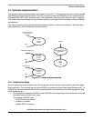
5.2.1.2 Phase Shift Synchronization
Phase shift synchronization synchronizes the generated PFC reference sine wave to the frequency of the
mains. It is realized by means of:
• Zero voltage crossing detection (zero voltage sensor)
The zero voltage crossing sensor generates a falling edge every time when the input voltage
crosses zero from positive to negative polarity.
• External interrupt
An external interrupt is triggered by the zero voltage crossing sensor. The interrupt subroutine is
used to get the content of timer TIM registers TCNTH:TCNTL for automatic microcontroller
trimming and for PFC reference sine wave amplitude gain calculation in lamp run mode.
• MCU oscillator frequency trimming
For microcontroller automatic trimming, the timer TIM is used as an interval counter. The timer is
incremented by the internal clock (divided by prescaler). Its content is cleared every
IRQ interrupt
produced by the voltage zero crossing sensor. A user defined value determines what number
should be found in TIM registers TCNTH:TCNTL. On the basis of the comparison between required
and actual counter values, the content of the oscillator trim register OSCTRIM is adjusted with
ramp.
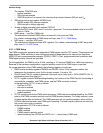
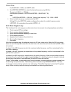
5.2.1.3 Reference Sine Wave Generation
Reference is performed by the PWM peripheral. The software contains a sine wave table with values for
interval and maximum amplitude. The amplitude of the sine wave depends on the value of the DC-bus
voltage and it is adjusted by the PI controller every 20ms. Two different sets of PI controller parameters
are used, one for MCU startup, when the DC-bus voltage must reach the required value quickly and HRP
is not activated, and the second during standard running operation.
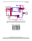
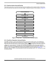
5.2.1.4 Generation of Output PFC Control SIgnal
The generated output PFC signal controls the PFC power MOSFET. An on-chip operational amplifier is
used in comparator mode. It compares the reference sine wave, filtered by the RC filter, with the actual
current and generates a switching signal for the PFC MOSFET transistor in the hysteresis current control
mode HW variation. In discontinuous conduction mode comparator output is used for switching off the
PWM1 signal. It works as a fault detection in fact. When the actual current sensed on the shunt resistor