


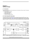

Software Implementation
Dimmable Light Ballast with Power Factor Correction, Rev. 1
Freescale Semiconductor 43
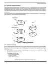
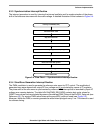
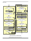
5.3.3 Synchronization Interrupt Routine
The interrupt procedure is used for trimming the internal oscillator and for synchronization of the phase
shift of the reference sine wave with the mains voltage. A detailed illustration of this is shown in
Figure 5-4.
interrupt void IRQisr(void)
End of subroutine
Clear IRQ flag
Run timer
Get actual timer value
Stop and reset timer
Enable trimming value calculation
Reset sine wave table pointer
Enable PI PFC stage regulator computing
Figure 5-4. Flow Chart — Synchronization Interrupt Routine
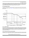
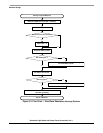
5.3.4 Sine Wave Generation Interrupt Routine
The PWM modulator is used to generate the reference sine wave for PFC control. The amplitude of
generated sine wave depends on output DC-bus voltage and it is calculated by means of PI regulator.
The phase shift of the sine wave is synchronized by means of
IRQ interrupt that is launched by input AC
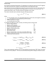
voltage zero crossing detector. The table bSinTab[PWM_RELOADS] contains duty cycle values for
PWM. These values can be calculated by means of worksheet PWM_Setup of the file DLB_Setup.xls (see
Reference [4]). For service PWM reload interrupt the pwmISR() routine is used (see Figure 5-5).
Moreover, inside the PWM, a counter generates a reload interrupt signal every 1 ms. This interval is used
for software timing.