


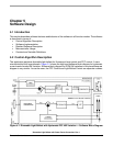

Software Design
Dimmable Light Ballast with Power Factor Correction, Rev. 1
42 Freescale Semiconductor
For BUSCLKX2 = 8 MHz, the HRPDT= $08
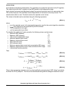
3. Set HRPPERH:HRPPERL to select the desired frequency (e.g. 88 kHz)
The period of 88 kHz = 1/88 kHz
Output period (seconds) = HRPPERH:HRPPERL / (BUSCLKX2 * 32)
then,
HRPPERH:HRPPERL = 1/88 kHz * (internal bus frequency * 32) = 2909 = $B5D
4. Select variable frequency mode and start the HRP
Writing $01 to the HRPCTRL register configures the module for variable frequency mode
(HRPODE = 0) and enables the module (HRPEN = 1).
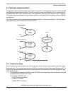
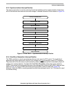
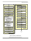
5.3.2 Main Program Loop
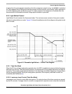
The functions of the main program can be broken down into several chronological phases, as follows:
1. Check required DC-bus voltage
2. Go to maximum ballast frequency
3. Apply maximum ballast frequency for start time
4. Go to preheat frequency
5. Apply preheat frequency for preheat time
6. Go to ignition frequency
7. Run mode
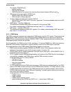
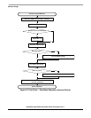
After the initialization stage, the software checks the DC-bus voltage value. When the DC-bus voltage
does not reach the required value within the start time or the value is out of limits then the faultISR routine
is launched.
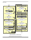
In phase 2, the HRP frequency is set to the maximum ballast frequency, and this is maintained for the
start time in phase 3.
In phase 4, the HRP frequency is ramped down to the preheat frequency, and this is maintained for the
preheat time in phase 5.
In phase 6, the HRP frequency is ramped down to the ignition frequency. If the minimum ballast frequency
is reached, then the controller tries again to ignite the lamps. If, in a defined number of attempts, the lamps
did not ignite, the ignition is interrupted and the faultISR routine is launched.
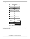
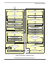
Phase 7 is Run mode - a never ending loop. During this phase, the required dimming value is sensed from
the dimming level potentiometer. The dimming value is sensed every ADDMININTERVAL. The tube
currents are measured every cycle in never ending loop. The ballast frequency is control by PI regulator
every 500us according required dimming level sensed from dimming potentiometer.