


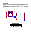

Control Algorithm Description
Dimmable Light Ballast with Power Factor Correction, Rev. 1
Freescale Semiconductor 37
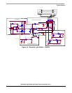
is higher than the generated sine waveform, then the comparator output is in log.1 and PWM1 is switched
off. This happens every PWM period and this process is called cycle by cycle limiting. PWM1 operates at
a 40 kHz frequency with variable duty cycle. For safety reasons, the comparator is enabled when the
microcontroller is initialized and mains voltage synchronization is provided.
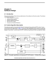
5.2.2 Light Ballast Control
Light Ballast Control controls the fluorescent tubes. The control process consists of two parts (modes),
tube start mode and tube run mode.
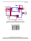
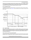
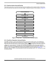
Figure 5-2 shows the software control time diagram during start mode
and run mode.
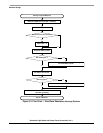
Figure 5-2. Dimmable Light Ballast — Control Time Diagram
5.2.2.1 Tube Start Mode
When the DC-bus voltage reaches the required value, the HRP is enabled at maximum ballast frequency
and kept for a set time. Then the ballast frequency is ramped down to the preheat frequency and kept for
a set time. This procedure preheats the filaments. In the next stage, the ballast frequency is ramped down
until the lamps are ignited. During the lamp ignition procedure, the frequency and tube currents are
controlled (see Reference [
4]).
5.2.2.2 Luminance Level Control (Tube Run Mode)
Luminance Level Control is active after tube ignition. The actual values of the tube currents are sensed
by the AD converter. Average value of currents is compared with required current value after luminance