


System Modules
Dimmable Light Ballast with Power Factor Correction, Rev. 1
Freescale Semiconductor 27
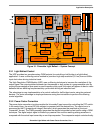
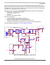
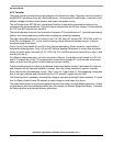
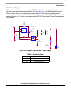
signal of the comparator (Comp Out) controls the power switch Q1 through the output buffer, which
consists of transistors Q2, Q3, and Q4, resistors R10, R13, R34, R35, R36, and R37, and capacitor C7.
For discontinuous conduction mode the comparator output is disconnected from the Q4 transistor gate.
The PWM1 pin is connected to the Q4 transistor gate.
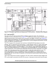
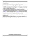
Digital PFC is driven by the MCU. The MC68HC908LB8 peripherals used for PFC are listed below:
• AD converter — channels ADC1 and ADC2
• PWM0 for generating sine wave
• comparator
• IRQ pin for zero-crossing detection
The PFC control algorithm
• converts the sensed output voltage to a digital value
• provides software PI regulator for a voltage feedback loop
• programs its PWM channel to create the pattern of the input current
• synchronizes operation with the mains frequency using mains zero-crossing detection
The control algorithm is described in 5.2 Control Algorithm Description.
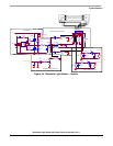
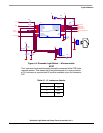
INPUT EMI FILTER AND BRIDGE RECTIFIER
COMPARATOR CIRCUIT
BUFFER CIRCUIT
DC-BUS VOLTAGE OUTPUT AND SENSING
BOOST CONVERTER
MAINS ZERO CROSSING SENSING
1
2
R34
0R
12
R10
6K8
12
R35
0R
12
R3
220K
C
B
E
Q2
BC846B
1
2
R5
220K
1
2
R7
220K
E
B
C
Q3
BC856B
R13
620R
GND
15V
C7
100nF
GND
PFC Gate
D15
BAT48
GND
C8
82pF
Zero Detect
1
2
R34
0R
12
R10
6K8
12
R35
0R
12
R3
220K
C
B
E
Q2
BC846B
1
2
R5
220K
1
2
R7
220K
E
B
C
Q3
BC856B
R13
620R
GND
15V
C7
100nF
GND
PFC Gate
D15
BAT48
GND
C8
82pF
Zero Detect
D2
BZV55C5V6
1 4
2 3
L6
CMFIL2
15V/1
53
L1B
PFCIND3
GND
GND
12
C1
10nF 275V X2
12
C2
150nF 275V X2
C10
220nF
1 2
C5
4n7 250/1000V Y2
2.7mH
5V
R36
0R
DC+
1
DC-
2
AC1
3
AC2
4
U1
DF1510S
R37
0R
D2
BZV55C5V6
1 4
2 3
L6
CMFIL2
15V/1
53
L1B
PFCIND3
GND
GND
12
C1
10nF 275V X2
12
C2
150nF 275V X2
C10
220nF
1 2
C5
4n7 250/1000V Y2
2.7mH
5V
R36
0R
DC+
1
DC-
2
AC1
3
AC2
4
U1
DF1510S
R37
0R
D
G
S
Q1
IRF820A
D1
MURS160T3
I1
1
I2
2
I3
3
NC
4
I5
5
I6
6
J1
PM100-INP_CONN-6
C3
10nF 630V TC356
12
+
C4
22uF 450V
1 2
R4 2R7
1
2
R12
10K
GND
12
RV1
275V
PFC Gate
1
2
R11
3K0
R14
2K0
PFC Current Sense
GND
PFC Current Sense
DCB
D
G
S
Q1
IRF820A
D1
MURS160T3
I1
1
I2
2
I3
3
NC
4
I5
5
I6
6
J1
PM100-INP_CONN-6
C3
10nF 630V TC356
12
+
C4
22uF 450V
1 2
R4 2R7
1
2
R12
10K
GND
12
RV1
275V
PFC Gate
1
2
R11
3K0
R14
2K0
PFC Current Sense
GND
PFC Current Sense
DCB
Comp -
12
R1
560K
12
R2
560K
12
R6
510K
12
R8
18K
C27
1n5
Comp Out
12
R9
47K
GND
C6
100nF
GND
1
2
JP6
CONN/HDR/2X1
GNDGND
D
G
S
Q4
MMBF0201
DCB Divider
GND
GND
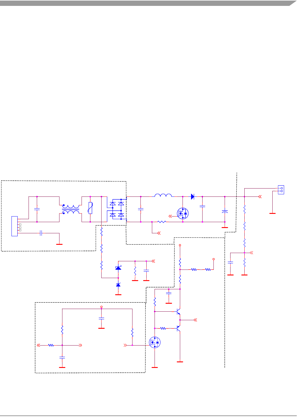
Figure 4-3. Dimmable Light Ballast — Input and PFC