


Software Design
Dimmable Light Ballast with Power Factor Correction, Rev. 1
52 Freescale Semiconductor
5.5.3 I/O Usage
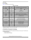
Table 5-2 summarizes the use of the I/O pins.
Table 5-2. I/O Usage
I/O pin Direction Purpose
PTC0/OSC1 INPUT OSC1(EXTERNAL OSCILLATOR IN MONITOR MODE)
PTC1/OSC2 - UNUSED
PTC2/SHTDWN/IRQ INPUT
IRQ (MAINS ZERO CROSSING DETECTION/ IRQ IN MONITOR
MODE)
PTB0/TOP OUTPUT TOP (HRP OUTPUT)
PTB1/BOT OUTPUT BOT (HRP OUTPUT)
PTB2/FAULT - UNUSED
PTB3/PWM0 OUTPUT PWM0 (REFERENCE SINUS WAVE GENERATING)
PTB4/PWM1 OUTPUT SWITCHING PFC TRANSISTOR ONLY IN DCM HW VARIATION
PTB5/V+ INPUT V+ (COMPARATOR INPUT)
PTB6/V- INPUT V- (COMPARATOR INPUT)
PTB7/VOUT/ADC6/FAULT OUTPUT
VOUT (COMPARATOR OUTPUT) AND MOREOVER AS PWM
FAULT PIN IN DCM HW VARIATION
PTA0/ADC0/KBI0 INPUT/OUTPUT
PTA0 (COMMUNICATION PIN IN MONITOR MODE AND FOR
SERIAL BOOTLOADER PROGRAMMING)
PTA1/ADC1/KBI1 INPUT ADC1 (LUMINANCE LEVEL /PTA1 IN MONITOR MODE)
PTA2/ADC2/KBI2 INPUT ADC2 (DC-BUS VOLTAGE)
PTA3/ADC3/KBI3 INPUT ADC3 (TUBE CURRENT 1)
PTA4/ADC4/KBI4 INPUT ADC4 (TUBE CURRENT 1
PTA5/RST/KBI5 OUTPUT PTA5 (USER LED)
PTA6/ADC5/TCH0/KBI6 INPUT ADC5 (TUBE VOLTAGE DIFFERENCE
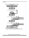
The installation CodeWarrior Version 3 Service Pack for LB8 is part of the Emulation Board software. This
includes examples of how to tune and work with the HRP.
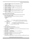
5.6 Definitions of Constants and Variables
This section provides definitions of the constants and variables used in the program. The definitions can
be divided into two parts:
• System setup definitions
• System constants and variables