


SYSTEM DESCRIPTION
PROANNOUNCE System User Handbook 1.1 3-1
3. System Description
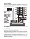
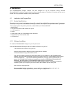
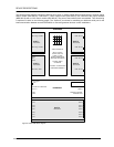
This chapter provides an overview of the general configuration of the PROANNOUNCE system and its most important
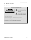
functions. The following block diagram shows a typical PROANNOUNCE system installation including the DPM 4000
central unit, paging stations, audio equipment, amplifiers, power supply unit, relay board assemblies, loudspeaker lines,
and control board assemblies for external signals.
figure 3.1 PROANNOUNCE System
3.1 General Overview
The digital PROANNOUNCE manager DPM 4000 represents the central unit of the system. It is used to control and
monitor all connected components via several serial interfaces. The chapter Single Device Descriptions contains all
necessary information about the DPM 4000 and its available modules.
The kind and amount of connected audio sound sources, amplifiers, and relay board assemblies are extremely
variable. This allows configuring the system to basically match any requirement. The system is capable of managing up
to 16 paging stations and up to 100 output lines. More than 150 control inputs and outputs are available for controlling
and monitoring purposes providing the possibility to generate and manage logic levels and analog levels as well. For
detailed information, please refer to the chapter DCS 400 Control System.
Configuration and documentation of a PROANNOUNCE system installation is established through the use of the
PROANNOUNCE Designer software – a comfortable graphical user interface that runs on a PC under Windows
95/98/NT. This allows changing the system’s setup at any time to meet new requirements, without the need to alter the
actual installation. The PC has to be connected to the system only when loading or changing its configuration. During