


DEVICE DESCRIPTIONS
PROANNOUNCE System User Handbook 1.1 5-45
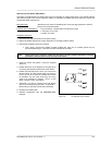
Optional Key-lock Switch (NRS 90231)
The paging consoles employ two empty slots for the incorporation of optional alarm keys or key-locked switches
(also refer to chapter 5.2.3 Control Panel DPC 4550). For retrofitting an additional key-lock switch you should only
use the NRS 90231 extension kit.
Brief description:
optional key-lock switch for retrofitting DPC 4xxx-type paging stations to work as
idling current-controlled opener.
Supplied with the NRS 90231:
1 key-lock switch, complete with front frame and 2 keys
1 connection cord, 4-pole
1 resistor 10 k ohms
Installation instruction:
1. Disconnect the paging console from the power supply.
2. Detach the bottom plate (6 to 8 screws, depending on the paging station model).
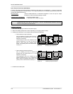
3. Prepare the installation site for the insertion:
· Use a sharp, pinpoint tool (needle, pointed rat-tailed file, knife etc.) to carefully pierce the pre-
punched holes through – from the front panel’s outside to the inside.
Note: Please make sure to solder the cables after the switch has been installed. Otherwise it is virtually
impossible to slide the milled nut over the body of the switch!
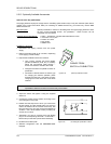
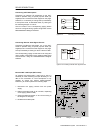
4. Adjust the switch and tighten it using the supplied
milled nut.
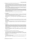
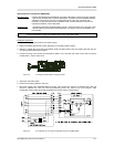
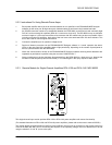
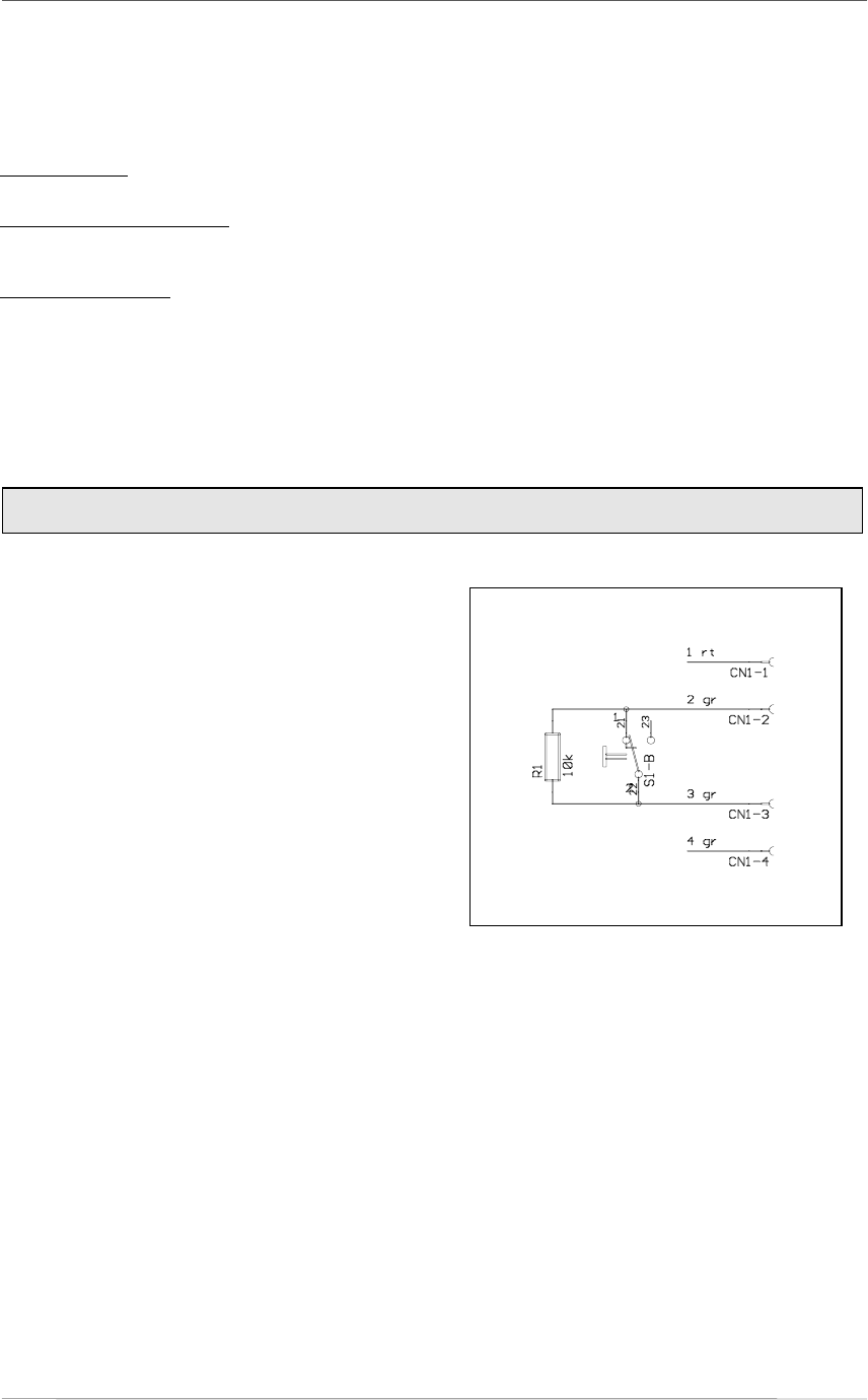
5. Please refer to the circuit diagram on this page when
connecting the supplied 4-pole wire and the resistor.
6. Please mind the sequence in which you connect the
flat wire cables. The two outside wires 1(rt) and 4(gr)
have to be cut off as short as possible and need to
be insulated. The two inner wires 2(gr) and 3(gr)
need to be soldered to contacts 1 and 2 of the
switch. Polarity is not a critical factor.
7. Afterwards, you have to connect the 4-pole female
plug to the corresponding OPTION 1 or OPTION 2 -
terminal strip on the basic printed board assembly.
8. Re-attach the bottom plate.
9. Software configuration with the PROANNOUNCE
Designer
figure 5.40 circuit diagram key-lock switch