


DEVICE DESCRIPTIONS
PROANNOUNCE System User Handbook 1.1
5-3
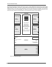
5.1.2 Front View
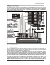
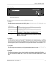
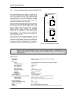
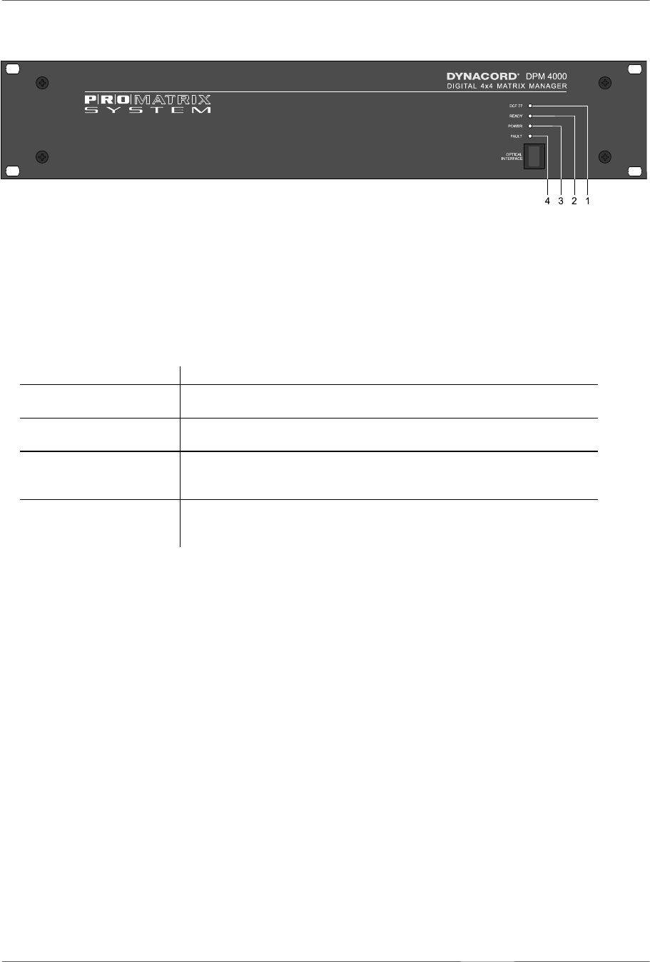
figure 5.2 DPM 4000 front view
The following controls and indicators are located on the DPM 4000's front panel:
1. LED DCF 77
This LED indicates the operation mode of the DCF 77 radio-controlled-signal receiver. The following table shows
the different indications and explains their corresponding status:
LED indication status
OFF
No radio control signal detected or no DCF 77 antenna connected. The
system clock is quartz-synchronized.
ON
The radio control signal is received. The system clock is synchronized
to the DCF 77 signal.
Blinking, one cycle per
second
The radio control signal is present and the system clock is being
synchronized. This procedure can take up to 2 minutes. After
synchronization is complete, the DCF 77 LED light continuously.
Blinking, fast
The radio control signal is detected but its reception is jammed. Re-
adjusting the DCF 77 antenna or choosing a location with improved
reception is recommended.
2. LED READY
This LED indicates the operation mode of the PROANNOUNCE System. After switching the power on, the READY
LED blinks while the system boots. Depending on the complexity of the installation blinking can take several
seconds. After successful initialization, the LED lights, signaling that the system is ready for operation. Whenever
erroneous operation – either in the DPM 4000 or in one of the connected components – is detected, the LED goes
out indicating that a system error occurred. When the system power is OFF, the READY LED is OFF as well.
3. LED POWER
This LED lights as soon as a power source (24 V =, power supply or battery) is connected to the DPM 4000. The
LED does not light when the DPM 4000's power supply is disconnected, switched off or fails.
4. LED FAULT
This LED lights during a reset or when an internal watchdog error is being detected within the DPM 4000. It also
indicates erroneous operation of external system components (power amplifiers, paging stations, relay boards, ...).
The LED is connected to the READY relay on the rear of the appliance, which allows remote indication of system
errors.