


DEVICE DESCRIPTIONS
5-54 PROANNOUNCE System User Handbook 1.1
5.4 DCS 400 Control System
5.4.1 Characteristics
DCS 400 Series modules increase the PROANNOUNCE system's control functionality in miscellaneous ways. These
printed board assemblies in the Europe standard format are usually inserted at the rear of a PA-system rack-shelf or
installed in suitable distribution boxes. The DCS 400 system consists of five different modules and additional
extensions:
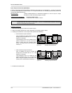
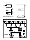
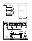
· DCS 401 control module for controlling relays, logic inputs, analog inputs and outputs, and rotary encoders
· DCS 408 relay module with 5 line relays for 100 V systems
· DCS 409 relay module with 5 NF or control relays
· DCS 412 logic input module with 12 floating, bi-polar inputs that are linked via opto-couplers
· DCS 416 analog I/O module offering 8 inputs and 8 outputs for 0 V DC to 10 V DC
· DCS 420 monitor module with 7-segment display, meter instrument and monitor loudspeaker
· NRS 90240 rotary encoder
A PROANNOUNCE installation allows integrating a maximum of up to 8 DCS 401 control modules. A single control
module can host up to 12 relay boards of the types DCS 408 / DCS 409 in any sequence. Besides, it is possible to
connect up to 5 logic input modules, 2 analog I/O modules, and 2 rotary encoders.
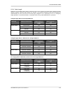
The PROANNOUNCE operating system defines the total amount of supported control inputs and outputs. The
PROANNOUNCE system can manage following amounts of different cards:
· Control module DCS 401 max. 8 boards = 16 rotary encoders
· Relays modules DCS 408 / DCS 409 max. 48 boards = 240 relays
· Logic input module DCS 412 max. 10 boards = 120 logic inputs
· Analog I/O module DCS 416 max. 8 boards = 128 analog inputs / outputs
· Monitor module max. 1 per DCS 401
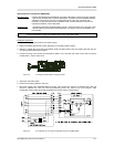
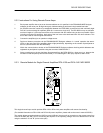
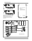
Note: The power supply of individual boards can be provided either via RJ-45 connection (DCS 401), flat-
wire cables (DCS 408, DCS 409, DCS 412, DCS 416) or via 2 binding posts (±24 V) that are
located on each board. The current that runs through the RJ-45 connection or the flat-wire cables
has not to exceed 1 A max. The current for modules that are connected to the DCS 401 via flat-
wire cables may not exceed 700 mA max. The connectors CN7, CN8, CN9 share an electronic
fuse. For higher currents, it is important that under all circumstances the binding posts are used
instead. When cascading several modules, it is necessary to provide the power supply anew via
binding post connection. Directly cascading up to 7 or 10 modules is admissible while taking power
consumption features of the different types of incorporated modules into consideration. All modules
need to be fed from a single power source! Data inter-exchange amongst modules has to be
established via flat-wire cabling.
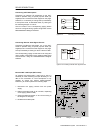
CAUTION: For safety reasons, DCS 400 modules may only be installed in rack-shelf systems or enclosures
that are locked and may only be opened by means of a tool (e.g. screw-driver, special key, etc.).
When installing modules, make sure to follow all requirements of the EN60065:1993 regulation.
Obeying the regulations for interference-emission (EN55022, class B) and interference-stability
(EN50082-2), DCS 400 module printed board assemblies need to be grounded at their fixing points
(e.g. using a metal bolt).