


APPENDIX
PROANNOUNCE System User Handbook 1.1
6-3
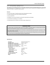
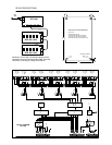
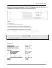
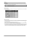
6.2 DMM 4650 Interconnection
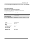
Interconnecting the DMM 4650 is established through control inputs and outputs on the DPM 4000 or on the DCS 400
monitoring system (DCS 408, DCS 409, DCS 412).
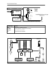
Every single sequence needs a control output for the start / stop command and a control input for the transmission of
the return signal. The control output starts the DMM 4650 sequence with a positive slope and stops it with a negative
slope. The return signal's control input reacts to the negative slope and activates the macro "Message Stop".
Additionally, in most cases a control input is needed for the DMM 4650 READY / FAULT signal. The following cabling
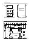
example offers a possibility for controlling three different sequences including fault recognition. This is accomplished by
utilizing Port A on the DMM 4650 and the 8 I/O control module (IN 5 - 8 and OUT 5 - 8) of the DPM 4000.
DMM 4650
FAULT
OUT1
OUT4
OUT3
OUT2
PORT A NRS 90219
DPM 4000
OUT5
OUT8
OUT7
OUT6
IN1
IN4
IN3
IN2
IN5
IN8
IN7
IN6
1
8
7
6
5
4
3
2
1
8
7
6
5
4
3
2
20
10
23
9
22
8
21
7
15
5
18
4
17
3
16
2
25
12
GND
11/19/241/6/
+24V
13
Sequenz 1
Sequenz 2
Sequenz 3
Stop
Sequenz 1
Sequenz 2
Sequenz 3
Fault
+24V
GND
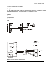
Using an adapter cable (2 x RJ-45 to 25-pole D-Sub), the shown cabling is established with relative little effort.
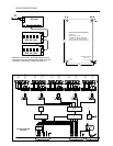
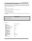
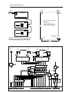
For a larger amount of sequences, it is necessary to additionally utilize Ports B, C, and D on the DMM 4650. Triggering
the sequence start / stop is accomplished through additional control outputs on the DPM 4000 control module (OUT 2 -
4) or via relay contacts on the DCS 408 respectively on the DCS 409 modules. The return signal is present at the
control inputs IN 1 - 4 of the DPM 4000 control module; additional control inputs can be provided via DCS 412
modules.
For controlling a DMM 4650 sequence, first you have to assign the start / stop and return message lines in the
PROANNOUNCE Designer software. Afterwards, defining the audio signals in the window “External Audio Signals
DMM 4650” is possible (the window opens when double-clicking onto the DMM 4650 symbol), where start / stop and
return message lines are assigned to individual audio signals. When this is done, starting a DMM 4650 sequence from
a paging console is already possible. Individual zones are assigned in the paging console dialog (key-assignment).
Defining additional triggers and zones is possible for the case that different events than a paging station keystroke
(external triggers, timer) are used to start a DMM 4650 sequence. Displaying text on the LCD during the output of a
DMM 4650 sequence is possible as well.
Programming examples for interconnecting the DMM 4650 are provided in the file Demo99_2.pmx, which is installed
during the installation of the PROANNOUNCE Designer software within the following directory:
/proannounce/examples/.