


DEVICE DESCRIPTIONS
PROANNOUNCE System User Handbook 1.1
5-27
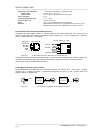
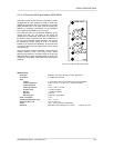
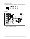
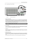
Pin-Assignment Of RJ-45 Connectors:
The floating control inputs and outputs provide 2 adjacent contacts, each. The following diagram shows the
assignment of RJ-45 contacts to inputs / outputs.
figure 5.32 pin-assignment of the IN / OUT connectors
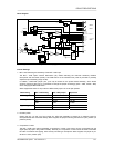
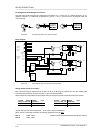
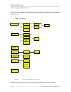
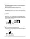
Block diagram:
DIGITAL
SUPPLY
BOARD
STATUS
& ID
SPI
+5V
+U24
BOARD
CONTROL
4
RES
IN1
IN8
IN7
IN6
IN5
IN4
IN3
IN2
OUT2
OUT8
OUT7
OUT6
OUT5
OUT4
OUT3
SLAVE
CLOCK
INPUT
REGISTER
OUTPUT
REGISTER
DATA BUS
D8 - D15
CONTROL
figure 5.33 block diagram of the 8 I/O control module
slave clocks