


DEVICE DESCRIPTIONS
PROANNOUNCE System User Handbook 1.1
5-6
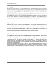
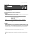
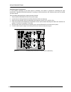
5. MONITOR OUTPUT socket
The audio signal of the integrated monitor amplifier is outputted via this connector. In standard configuration, this
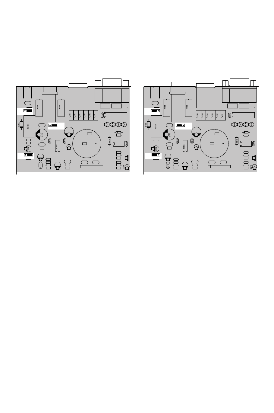
output is set for the connection of headphones. It is also possible to directly connect a loudspeaker with minimum
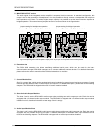
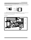
load impedance of 8 Ohms. To achieve higher output capacity it is possible to set the internal monitor amplifier to
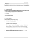
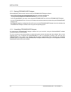
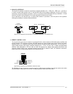
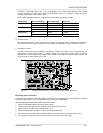
bridged operation. Thus some internal jumpers have to be re-set as shown in the figure below.
jumper-setting for headphones operation jumper-setting for bridged operation
figure 5.6 adjusting the monitor amplifier's output power via jumpers on the printed board assembly 80430
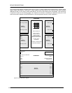
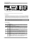
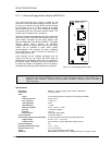
6. Extension slot
The DPM 4000 extension slot allows retrofitting additional serial ports, which can be used for the inter-
communication amongst DPM 4000 managers or to connect additional external devices. For detailed information,
please refer to the owner’s manuals of the individual extensions or modules.
7. Control Module Slot
Slot 5 is a control slot, which can be equipped with control modules for general control and query purposes. Control
modules provide different kinds of control inputs and outputs. For detailed description, please refer to the following
chapters. The DPM 4000 is shipped with one 8 I/O control module installed.
8. Slots for Audio Output Modules
The slots 3 and 4 are the DPM 4000's audio output slots providing two audio outputs per slot. Each slot can be
equipped with a 2-channel audio output module. The DPM 4000 is shipped with a 2-channel audio output module
installed in slot 3; described in detail at a later stage. Slot 4 is empty.
9. Audio Input Module Slots
The slots 1 and 2 are the DPM 4000's audio input module slots providing two audio inputs per slot. Each slot can be
equipped with any suitable audio input module. A detailed description of available audio input modules can be
found in the following chapters. The DPM 4000 is shipped with no audio input modules installed.
C142
C141
81
CN101
D204
C140
C139
C113
C110
JP101
JS101
R211
96
51
CN201
R228
R227
R117
R114
R122
R118
R121
C115
R120
R102
R101
R216
T101
FL201 FL202
IC201
IC204
C203 C201 C202 C204
C101 C102
C108
RN101
R110
R108
R107
R213
R212
R210
321
JP103
321
JP102
321
C142
C141
81
CN101
D204
C140
C139
C113
C110
JP101
JS101
R211
96
51
CN201
R228
R227
R117
R114
R122
R118
R121
C115
R120
R102
R101
R216
T101
FL201 FL202
IC201
IC204
C203 C201 C202 C204
C101 C102
C108
RN101
R110
R108
R107
R213
R212
R210
321
JP103
321
JP102
321
Jumper-Einstellung für Kopfhörerbetrieb Jumper-Einstellung für Brückenbetrieb