


DEVICE DESCRIPTIONS
PROANNOUNCE System User Handbook 1.1
5-13
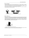
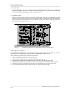
In addition, a MIC/LINE jumper (JP1, pins 5-6) is located on the printed board assembly, which allows
correctly configuring the input. When changing the MIC/LINE switch it is important to change the jumper
correspondingly (open = LINE, closed = MIC).
When shipped, the factory preset is: switch S1 in the LINE position and jumper JP1 open.
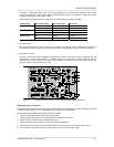
GAIN setting MIC / LINE setting MIC / LINE jumper Input level
Left margin
MIC Closed -14 dBu
LINE Open +16 dBu
Center position
MIC Closed -28 dBu
LINE Open +2 dBu
Right margin
MIC Closed -54 dBu
LINE Open -24 dBu
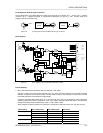
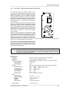
3. Phantom Power
By closing the jumper JP1, pins 1-2 and pins 3-4, engage 24 V phantom power is possible for microphones
that are directly connect. When shipped, the jumpers' factory preset position is “open” (no phantom power).
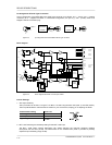
4. Compressor / Limiter
The MIC / LINE input channel embodies a compressor / limiter circuit which can be incorporated into the
signal path via jumper JP2 (position 1-2, COMP). Normally, the compressor / limiter should be used to
eliminate the risks of overdrive and clipping, when directly connecting a microphone. When shipped, the
jumper is set to its “Linear” position (2-3, LIN).
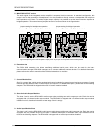
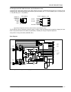
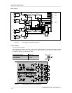
figure 5.14 retrofitting the input transformer, internal settings, location of parts (NRS 90216)
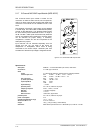
Retrofitting Input Transformers:
In case galvanic separation of the audio signal is necessary, an input transformer can be retrofitted to channel B
of the MIC / LINE module. This is accomplished using the extension kit NRS 90233.
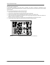
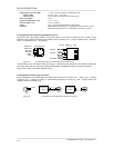
When retrofitting input transformers, please proceed as follows:
1. Disconnect the DPM 4000 from the mains power supply.
2. Loosen the two locking screws and carefully slide the module out of the slot.
3. Remove the two resistors of input channel B (R7 / R11).
4. Solder the transformer in position T1 onto the printed board assembly.
5. Re-insert the module into the slot and carefully push it into the DPM 4000 until it firmly locks in place.
6. Fix the module in place using the two locking screws and reconnect the power supply.