


APPENDIX
PROANNOUNCE System User Handbook 1.1
6-2
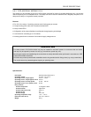
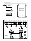
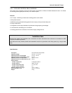
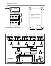
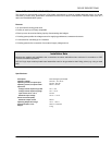
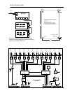
2. Voltage Supply
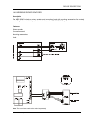
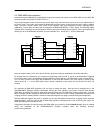
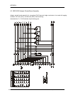
➨ Insert bridges serve to select the voltage supply connector of different modules. Please refer to the corresponding
description of individual modules or to their block diagrams.
CAUTION: The maximum current handling capacity of RJ-45 connections and flat-wire cables has to be
observed under all circumstances!
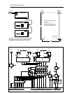
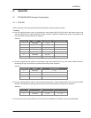
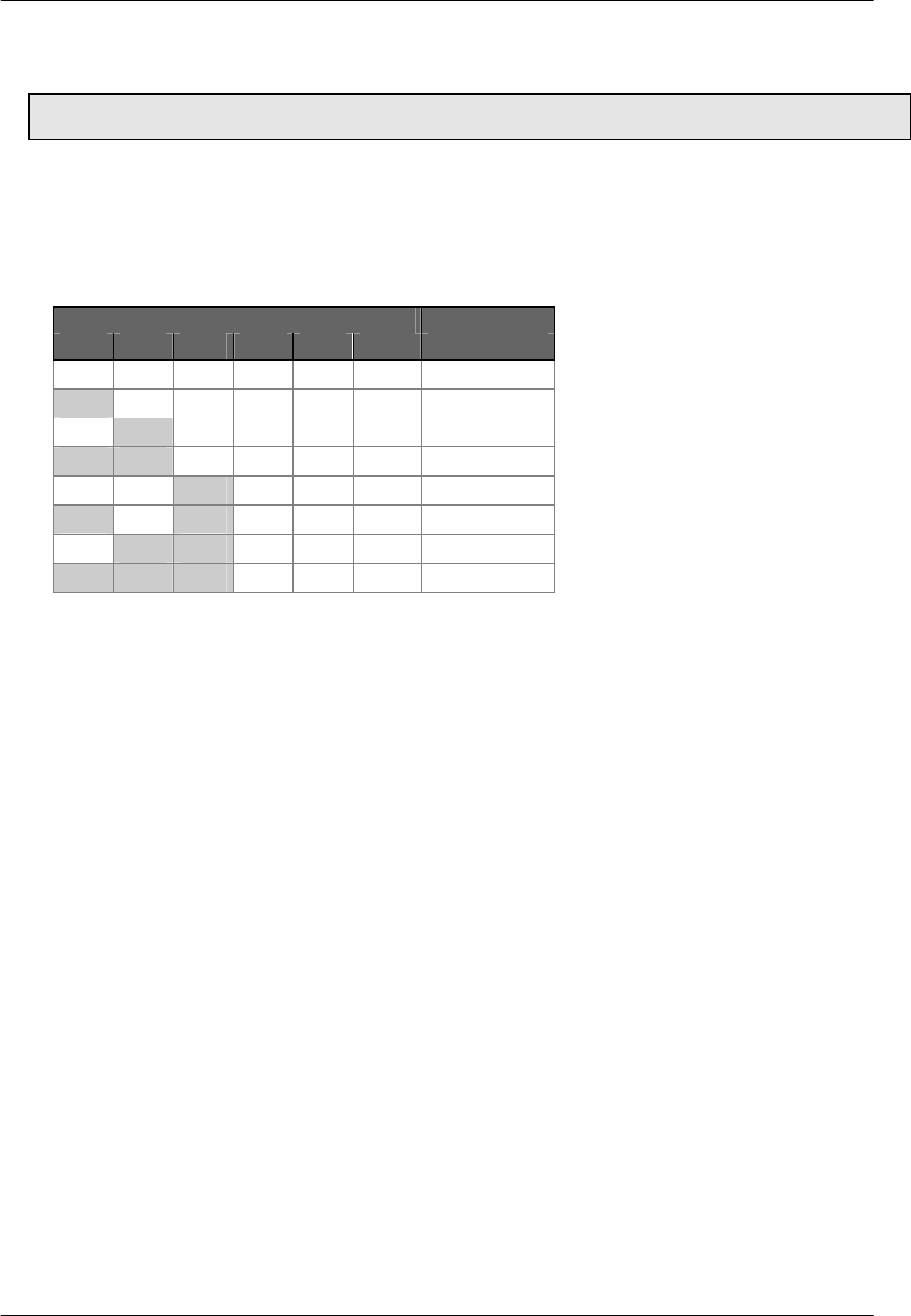
3. DCS 401 Addresses
➨ Using the Dip switch S1, the addresses of all connected control modules DCS 401 have to be set to different
numbers (addresses 0 - 7).
Dip switch S1 Address
1 2 3 4 5 6
OFF OFF OFF OFF OFF OFF 0
ON OFF OFF OFF OFF OFF 1
OFF ON OFF OFF OFF OFF 2
ON ON OFF OFF OFF OFF 3
OFF OFF ON OFF OFF OFF 4
ON OFF ON OFF OFF OFF 5
OFF ON ON OFF OFF OFF 6
ON ON ON OFF OFF OFF 7
4. Before initial operation
➨ Connect a 24V source. Now, each DCS 401 control module verifies whether any local modules (DCS 408, DCS
409, DCS 412, DCS 416) are connected, and if so, how many. The red LED blinks when the initialization process
has not been performed yet.
➨ Only for DCS 401 control modules with software version previous to V1.1: Each
DCS 401 control module is initialized by pressing the S2 button for approximately 3 seconds. Afterwards, the red
LED has to light continuously signaling that initialization was successfully completed.
➨ Launch netscan (menu communication / netscan within the PROANNOUNCE Designer software). Now, the DCS
401 modules are being initialized. Afterwards, the DPM 4000 runs a test verifying all addresses and recognizes the
amount of DCS 401 control modules installed in the system. All components sharing the network are listed in the
component list. This procedure takes approximately 20 seconds. Afterwards, the system is ready for operation.