


DEVICE DESCRIPTIONS
5-58 PROANNOUNCE System User Handbook 1.1
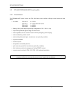
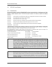
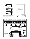
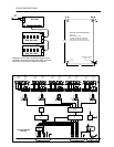
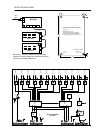
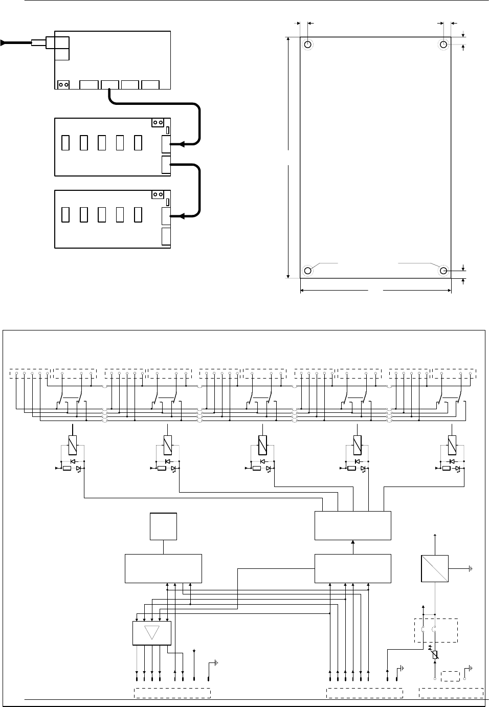
Maximally 12 DCS 408 / DCS 409 modules can be
cascaded. Using the insertion bridge CN3, select the
connection of the supply voltage (CN1/CN15).
RS
485
CN4
24V-
CN12 CN7 CN8 CN9
DCS 401
24V-
CN15
CN1CN2
CN3
DCS 408 / 409
24V-
CN15
CN1CN2
CN3
DCS 408 / 409
5
5
100
160
Æ
4,2
5 5
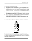
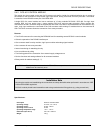
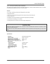
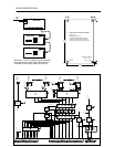
Dimensions of the DCS 408 module
Size in mm
Module height 20 mm
The distance between the soldered
surface and an electrical conductive
mounting base has to be at least 5 mm
Mounting insulators
max
Æ
7,5
P/S ID
DC
DC
+24V
t
+5V
A
B
C
+24V
Ar
Aa
Br
Ba
C
A
B
C
+24V
Ar
Aa
Br
Ba
C
A
B
C
+24V
Ar
Aa
Br
Ba
C
A
B
C
+24V
Ar
Aa
Br
Ba
C
A
B
C
+24V
Ar
Aa
Br
Ba
C
Relay
Driver
S/P
100V
Input 5
CN13
100V
Output 5
CN12
+24V
A
B
INPUT
CN1
+24V
CN
RESET
EN P/S
EN S/P
DATA
DATA
CLK
RESET
EN P/S
EN S/P
DATA
DATA
CLK
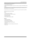
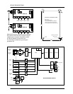
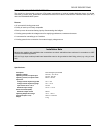
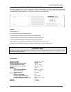
BLOCK DIAGRAM
DCS 408
OUTPUT
CN2
+24V
KL
-24V
KL
Jumper
CN3
CN15
100V
Input 4
CN11
100V
Output 4
CN10
100V
Input 3
CN9
100V
Output 3
CN8
100V
Input 2
CN6
100V
Output 2
CN7
100V
Input 1
CN5
100V
Output 1
CN4