


DEVICE DESCRIPTIONS
PROANNOUNCE System User Handbook 1.1
5-12
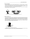
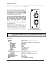
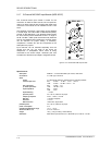
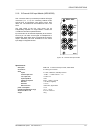
Pin-Assignment Of XLRF-Type Connectors:
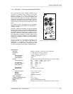
The pin-assignment of the MIC/LINE input's XLRF-type connector is as follows: pin 1 = screen, pin 2 = positive
conductor, pin 3 = negative conductor. In unbalanced configuration, the pins 3 (-) and 1 (screen) have to be
bridged inside the connection plug.
figure 5.12 pin-assignment of the MIC/LINE IN XLRF-type connector
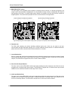
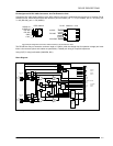
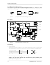
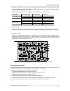
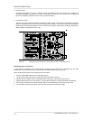
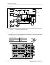
Block diagram:
MCLK
BCLK
WCLK
DIN
ANALOG
SUPPLY
DIGITAL
SUPPLY
BOARD
STATUS
& ID
SPI
INTERNAL MONITOR
+12V
-12V
+5V
+24V
BOARD
CONTROL
4
2 CHANNEL
DIGITAL
AUDIO
RES
A
D
IN A
PILOT
NRS 90233
IN B
L
AUX 1
R
L
AUX 2
R
12
3
+24V
MIC
LINE
LINE
MIC
COMPRESSOR /
LIMITER
MIC/
LINE
AUX 1
AUX 2
PILOT B
PILOT A
MON B
MON A
GAIN
AUX 2
GAIN
AUX 1
GAIN
JP2
LIN
COMP
JP1
5 6
JP1
1
2
3
4
figure 5.13 block diagram MIC/LINE + 2 AUX input module
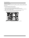
Internal Settings:
1. AUX input sensitivity
The input levels can be set in a range of -10 dBu to +12 dBu using trimmers VR2 (AUX 1) and VR3 (AUX 2).
The trim-potentiometers’ coarse scales are meant for your convenience, helping you in adjusting the levels.
Potentiometer setting Input level
Left margin
+12 dBu
Center position
-3 dBu
Right margin
-10 dBu
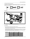
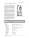
2. MIC / LINE switching and sensitivity setting for the MIC / LINE input
The MIC / LINE input's internal PAD-switch (S1) allows switching the channels' sensitivity between
microphone and line level (30 dB). The GAIN-control on the module's front panel is provided to precisely
adjust the input sensitivity (range 40 dB).
MIC/
LINE
IN
1
3
2
SHIELD
--
+
BALANCED
1
3
2
LO (-)
HI (+)
SOURCE
UNBALANCED
1
3
2
SOURCE