


DEVICE DESCRIPTIONS
PROANNOUNCE System User Handbook 1.1
5-20
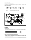
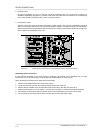
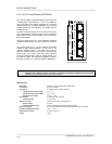
supply output for the DPC 4000
1, short-circuit-proof, electronic, programmable fuse
supply voltage
24 V DC (21.6 ... 31.2 V DC)
nominal current 330 mA, 660 mA, 990 mA (set via electronic fuse)
power consumption
2.5 W
operational temperature range
+5 °C ... +40 °C
dimensions W x H x D
37.5 x 81 x 252 mm
weight
165 g (215 g including NRS 90208 + NRS 90233)
extensions
NRS 90208 input transformer for 1 paging station input, order No. 121 641
NRS 90233 input transformer for 1 MIC/LINE input, order No. 121 682
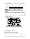
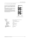
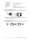
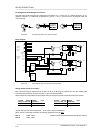
Pin-Assignment Of RJ-45 Socket And Extension Cord:
Connecting DPC 4000 paging stations to the DPC 4000 IN connector is performed using common RJ-45
extension cords, where the conductors are twisted in pairs as follows: pair 1 = 1/2 (24 V/GND), pair 2 = 3/6 (free),
pair 3 = 4/5 (RS-485), pair 4 = 7/8 (AUDIO).
figure 5.23 pin-assignment of the DPC 4000 socket, RJ-45 extension cord
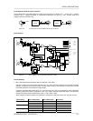
The RS-485 bus may not exceed a maximum length of 1,000m (mind the voltage drop for operation voltage) and
must follow a line-structure (short stub cables are permissible). Twisted-pair wiring is of special importance.
Using IY(ST)Y wiring is allowable (38400 Bd, 9N1)
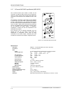
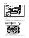
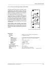
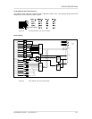
Pin-Assignment Of XLRF-Type Connectors:
The pin-assignment of the MIC/LINE input's XLRF-type connector is as follows: pin 1 = screen, pin 2 = positive
conductor, pin 3 = negative conductor. In unbalanced configuration, the pins 3 (-) and 1 (screen) have to be
bridged inside the connection plug.
figure 5.24 pin-assignment of the MIC/LINE IN XLRF-type connector
MIC/
LINE
IN
1
3
2
SHIELD
--
+
BALANCED
1
3
2
LO (-)
HI (+)
SOURCE
UNBALANCED
1
3
2
SOURCE
DPC 4000 IN
+24V
GND
RS-485 +
A
UDIO IN -
A
UDIO IN +
RS-485 -
1
8
8
7
6
5
4
3
2
1
RJ-45 e
x
tens
io
ncord
A
UDIO
RS-485
24V/GND