


APPENDIX
PROANNOUNCE System User Handbook 1.1
6-1
6. Appendix
6.1 PROANNOUNCE Hardware Configuration
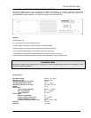
6.1.1 DCS 400
When configuring and initially operating the DCS 400 system, please proceed as follows:
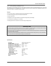
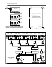
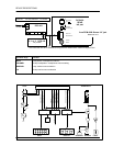
1. Cabling
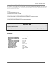
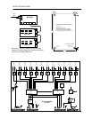
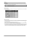
➨ Use the supplied flat-wire cable for connecting the relay modules DCS 408, DCS 409 in the desired order to the
control module DCS 401. Mixed installation of relay modules is possible; numbering the relays is type-specific and
has to be performed according to their sequence.
example:
Sequence Module Line relay No. Control relay No.
1 DCS 408 1 - 5
2 DCS 408 6 - 10
3 DCS 409 1 - 5
4 DCS 408 11 - 15
5 DCS 409 6 - 10
6 DCS 408 16 - 20
... ... ... ...
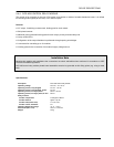
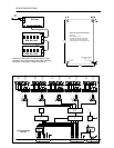
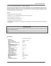
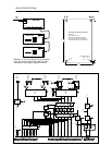
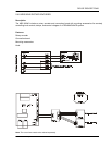
➨ Use the supplied flat-wire cable for connecting the logic input module DCS 412 to the control module DCS 401.
Numbering the logic inputs has to be performed according to their sequence.
example:
Sequence Module Logic input No.
1 DCS 412 1 - 12
2 DCS 412 13 - 24
3 DCS 412 25 - 36
... ... ...
➨ Use the supplied flat-wire cable for connecting the analog input / output modules DCS 416 to the control module
DCS 401. Numbering the analog inputs and outputs has to be performed according to their sequence.
example:
Sequence Module Analog input No. Analog output No.
1 DCS 416 1 - 8 1 - 8
2 DCS 416 9 - 16 9 - 16
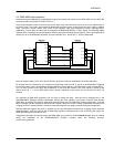
➨ Connect the control module DCS 401 via RJ-45 cable to the REMOTE CONTROL socket on the DPM 4000.