


DEVICE DESCRIPTIONS
PROANNOUNCE System User Handbook 1.1
5-5
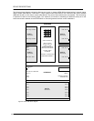
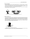
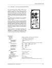
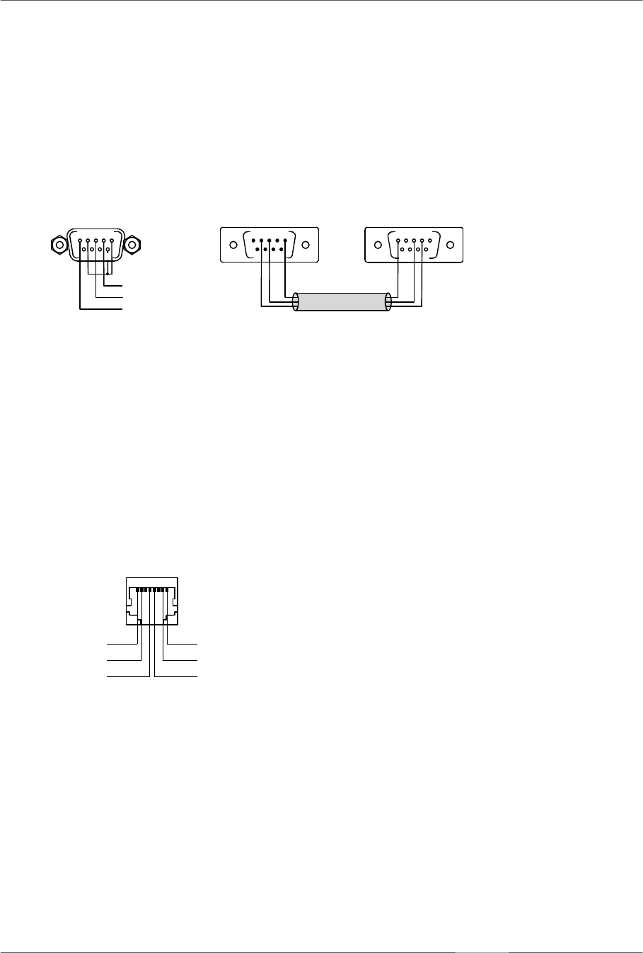
3. RS-232 PC INTERFACE
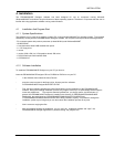
This 9-pole PC-interface is meant for connecting a computer (female, pin 4 = TXD, pin 3 = RXD, pin 1 = ground). It
is used to transfer data between the PC and the DPM 4000 during system configuration as well as for control,
monitoring, and remote diagnosis purposes. The PC is connected to the DPM 4000 utilizing a standard 1:1 D-sub
extension cord with male connectors on one end and female connectors on the other.
As an alternative to the RS-232 port, an optical IrDA interface is provided on the front panel of the appliance
offering the possibility for wireless data transmission.
figure 5.4 pin-assignment of the RS-232 PC INTERFACE connector, D-Sub extension cord
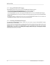
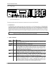
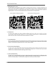
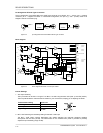
4. REMOTE CONTROL socket
This 8-pole RJ-45-type socket is meant for connecting DCS 401 control modules or DPA 4000 power amplifiers with
remote interface. The connector provides a RS-485 interface for communicating with control modules and power
amplifiers (pins 4 / 5), a balanced audio input for the insertion of external monitor signals (pins 7 / 8), and a 24 V==
supply voltage output for the supply of external modules (pin 1 = +24 V, 1 A max., pin 2 = GND). A programmable
electronic fuse (adjustable to 330 mA, 660 mA, 990 mA) protects the voltage output against short-circuit and
overload. External devices are connected through common RJ-45 extension cords. For additional information,
please refer to the corresponding chapters of the individual device.
figure 5.5 pin-assignment of the REMOTE CONTROL socket
The RS-485 bus may not exceed a maximum length of 1,000m and must follow a line-structure (short stub cables
are permissible). Cabling has to be carried out using twisted pair cables (38.400 Bd, 8N1)
CONTROL
REMOTE
+ 24V
GND
RS-485 +
AUDIO IN -
AUDIO IN +
RS-485 -
18
PC INTERF
A
CE
RS-232
987
6
12345
TxD
RxD
M
A
SSE
678
54321
9 987
6
12345
RS-232
extension cord