


DEVICE DESCRIPTIONS
PROANNOUNCE System User Handbook 1.1 5-51
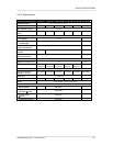
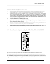
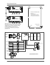
5.3.2 Instructions For Using Remote-Power Amps:
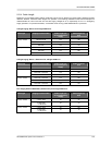
1. Each power amplifier has to be set to the exact address as it is specified in the PROANNOUNCE Designer
software (A=low value part, B=high value part). Address setting is performed using hexadecimal code.
2. An RS-485 connection needs to be established between the DPM 4000 (remote socket) and maximally eight
DCS 401, and maximally 64 amplifiers (DPA 4411 counts as a single unit). The RS-485 bus may not exceed a
maximum length of 1,000m and must follow a line-structure with stub cables being as short as possible. When
including more than 30 amplifiers, both ends of the bus have to be terminated with 120 ohms resistors. This
bus is also used for monitor signal transmission.
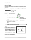
3. Connect the amplifier(s) to an operation voltage source.
4. Perform a Netscan procedure via the PROANNOUNCE Designer software. In ‘normal’ operation the status-
LED’s on the rear panel of the amplifiers have to light periodically, depending on the number of participants on
the bus (communication with the DPM 4000).
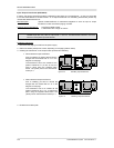
5. Within the communication window of the PROANNOUNCE Designer software checking which addresses are
registered as participants is possible using the command “/AMP/AVLBL ?”.
6. Once a participant on the bus had been disconnected from the DPM 4000 for a short term (e.g. because the
RS-485 line had temporarily been disconnected), it is included again in the query sequence after 10 sec.
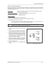
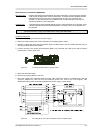
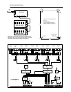
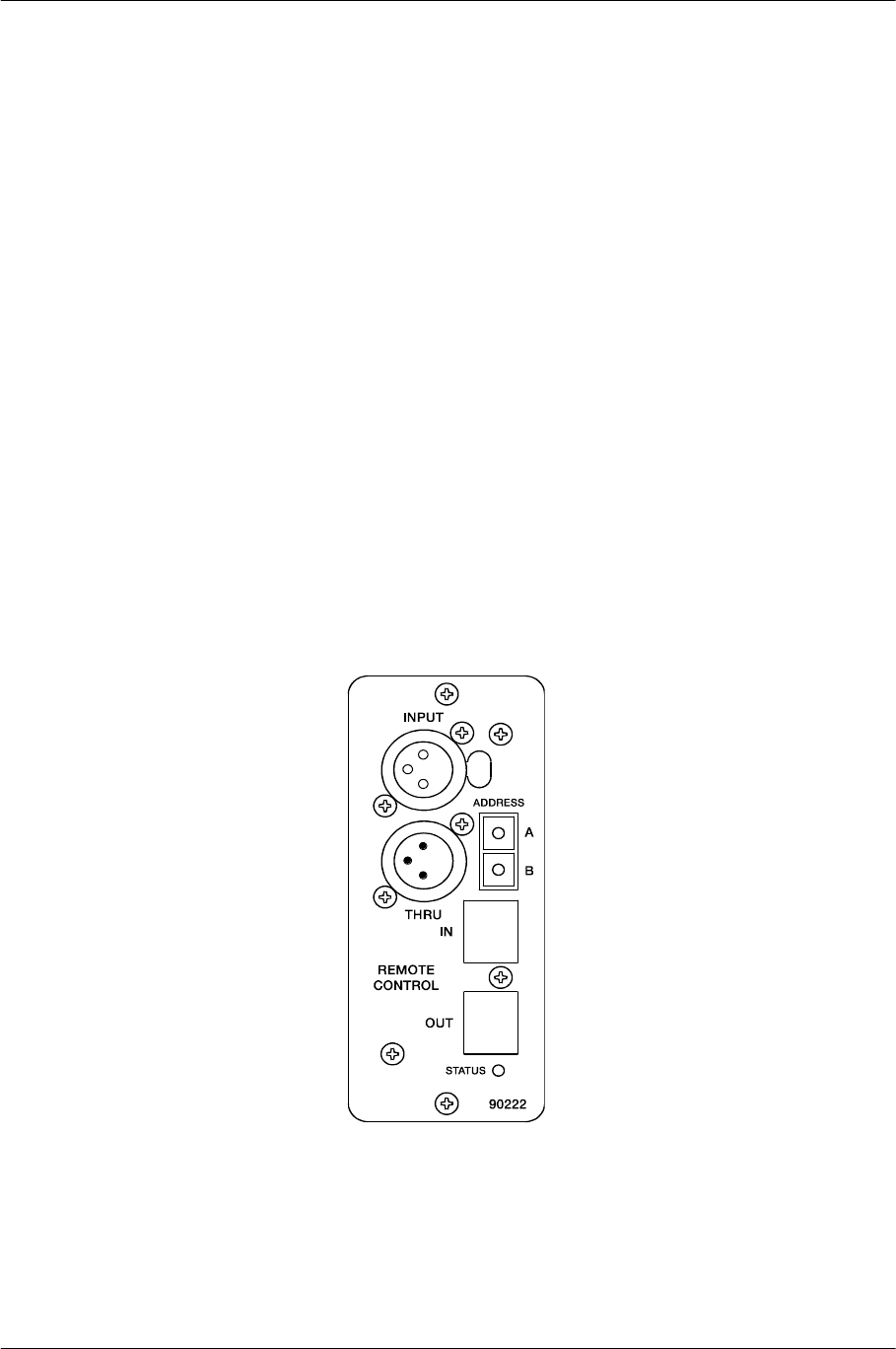
5.3.3 Remote Module for Single-Channel-Amplifiers DPA 4120 and DPA 4140 NRS 90222
This single-channel input module provides DPA 4120 or DPA 4140 power amplifiers with remote functionality.
(For detailed information on DPA 4120 and DPA 4140 power amplifiers, please refer to the owner’s manual 355768.)
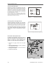
The module allows connecting balanced XLR-input and XLR-thru lines as well as connection to the remote control bus
of the DPM 4000 (RS-485). Prior to connecting the amplifier to the operating voltage, the unit’s address has to be set
using the switches “A” and “B” (A=low value part)