


DEVICE DESCRIPTIONS
PROANNOUNCE System User Handbook 1.1
5-2
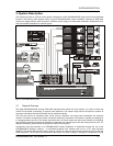
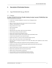
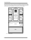
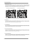
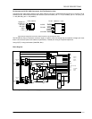
The following block diagram outlines the features once again. It shows a DPM 4000 equipped with a 2-channel paging
station module (NRS 90215), a MIC/LINE + 2 AUX inputs module (NRS 90216), two 2-channel LINE output modules
(NRS 90218) and an 8 I/O control module (NRS 90219). The ports of the interface block are standard. Their functioning
is explained in detail on the following pages. The "Optional" port allows for retrofitting an additional serial port for the
intercommunication between several DPM 4000s or connecting external devices / entire installations.
AUDIO MATRIX 4x4
INPUT FILTERS
OUTPUT DELAYS
CHIME / ALARM
SIGNAL GENERATOR
MESSAGE RECORDER
SYSTEM TIMER
CALENDAR
CONTROL / SUPERVISION
POWER MANAGEMENT
INTERFACE
DC INPUT
24V =
IN A
IN B MIC / LINE
SLOT 2
NRS 90216
AUX1
AUX2
IN A Pag. Console
IN B Pag. Console
SLOT 1
NRS 90215
LINE OUT A
SLOT 3
NRS 90218
LINE OUT B
LINE OUT A
SLOT 4
NRS 90218
LINE OUT B
+
RS-232 PC INTERFACE
DCF 77
INP 1
INP 2
OPTION PORT
READY
REMOTE CONTROL
MONITOR OUT
+ 24V =
SLOT 5
NRS 90219
IN 1 SLAVE CLOCK OUT 1
IN 8
IN 7
IN 6
IN 5
IN 4
IN 3
IN 2 OUT 2
OUT 8
OUT 7
OUT 6
OUT 5
OUT 4
OUT 3
DPM 4000
figure 5.1 DPM 4000 block diagram