


DEVICE DESCRIPTIONS
PROANNOUNCE System User Handbook 1.1
5-9
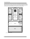
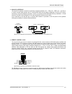
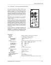
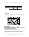
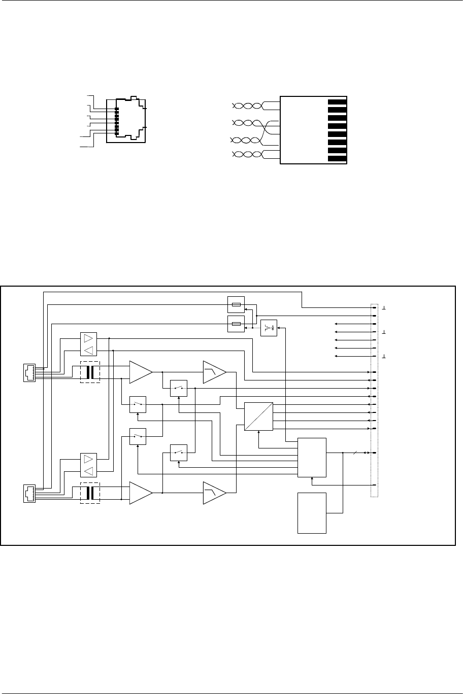
Pin-Assignment Of DPC 4000 Connectors And The Extension Cord:
Connecting DPC 4000 paging stations to the DPC 4000 IN connector is established through the use of common RJ-45
extension cords, where the conductors are twisted in pairs as follows: pair 1 = 1/2 (24 V/GND), pair 2 = 3/6 (free), pair
3 = 4/5 (RS-485), pair 4 = 7/8 (AUDIO).
figure 5.8 pin-assignment of the DPC 4000 connectors, RJ-45 extension cords
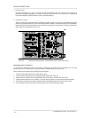
The RS-485 bus may not exceed a maximum length of 1,000m (mind the voltage drop for operation voltage) and must
follow a line-structure (short stub cables are permissible). Twisted-pair wiring is of special importance.
Using IY(ST)Y wiring is allowable (38400 Bd, 9N1)
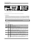
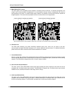
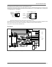
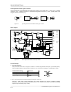
Block Diagram:
MCLK
BCLK
WCLK
DIN
ANALOG
SUPPLY
DIGITAL
SUPPLY
BOARD
STATUS
& ID
SPI
INTERNAL MONITOR
+12V
-12V
+5V
+U24
BOARD
CONTROL
4
2 CHANNEL
DIGITAL
AUDIO
RES
A
D
AUDIO
RS-485
NRS 90208
ELECTRONIC
PROGRAMMABLE
FUSES
24V
DPC 4000
IN A
PILOT
AUDIO
RS-485
NRS 90208
24V
RX485
TX485
DPC 4000
IN B
PILOT A
PILOT B
MON A
MON B
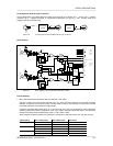
figure 5.9 block diagram 2-channel paging station module
DPC 4000 IN
+24V
GND
RS-485 +
AUDIO IN -
AUDIO IN +
RS-485 -
1
8
8
7
6
5
4
3
2
1
RJ-45 e
x
tens
io
ncord
AUDIO
RS-485
24V/GND