


DEVICE DESCRIPTIONS
PROANNOUNCE System User Handbook 1.1
5-4
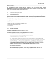
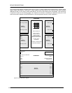
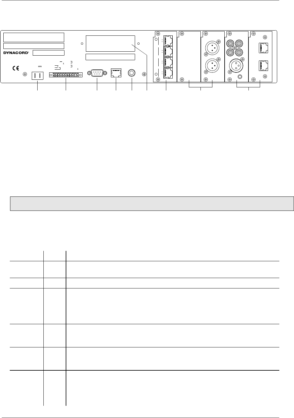
5.1.3 Rear View
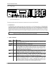
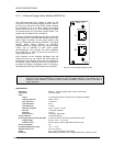
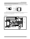
figure 5.3 DPM 4000 rear view
The following module ports and connections are located on the rear panel of the DPM 4000:
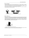
1. DC INPUT 24V ==
The DPM 4000's power supply source has to be connected here; a 24 VDC power supply or a PROANNOUNCE
system battery module using insulated AMP flat-connector plugs 6.3 x 0.8 mm. The DPM 4000 is protected against
polarization mismatch and all positive and negative conductors within the device are fuse-protected. The fuses are
located inside the enclosure on the printed board assembly 80430. The connection cables have to be 1,5 mm
2
in
diameter at least. With this diameter the cable length of a single path should not exceed 4.0 m (max. drop in voltage
<1V).
CAUTION: Using the DPM 4000 is only permissible with batteries that are not grounded or provide a grounded
negative pole. Operation with grounded positive pole is not admissible.
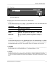
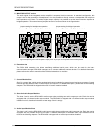
2. SIGNAL INTERFACE
Signal Pins Description
+24V ==
1 24 V== voltage output for the supply of external components. The maximum current
handling capacity is 400 mA.
GROUND
2 Ground connector of the 24 V== voltage output.
READY
3, 4, 5 Floating output for the indication of the system's operation mode. In the normal ready
mode the READY relay is activated. When internal errors occur or external devices
show faulty behavior, the READY-relay drops. The relay is connected to the FAULT
LED indicator on the front panel of the DPM 4000 providing indication of the
operational status directly on the appliance.
INP1
6, 7 Floating input for monitoring / remote controlling the battery power supply, usually
connected to a battery module or battery charging unit. Since this input can be freely
programmed, using it for any other 24 V control signal is possible as well.
INP2
8, 9 Floating input for monitoring / remotely controlling the power supply, usually
connected to the 24 V== system power supply. Since this input can be freely
programmed, using it for any other 24 V control signal is possible as well.
DCF77
10, 11 Socket for connecting an external DCF 77 antenna. This input provides the supply
voltage and simultaneously serves as input for the decoded DCF 77 signal. Only
connecting the NRS 90193 DCF 77 receiver is admissible while polarity is not a
critical factor. However, according to CE regulations, shielded cabling has to be used.
Connect the shield to the connector's pin 10 and the signal line to pin 11.
+--
DC INPUT
24
MONITOR OUT
5
3
2
+ 24V
4
READY
GROUND
1
7
6
INP 1
9
8
11
10
INP 2
DCF 77 IN
111
PC INTERFACE
RS-232
CONTROL
REMOTE
WARNING:
TO REDUCE THE RISK OF FIRE OR ELECTRIC SHOCK,
DO NOT EXPOSE THIS APPLIANCE TO RAIN OR MOISTURE.
AV IS :
RISQUÉ DE CHOC ELECTRIQUE. NE PAS OUVRIR.
NO USER SERVICEABLE PARTS INSIDE. REFER SERVICING TO
QUALIFIED SERVICE PERSONNEL.
123
4
5
SIGNAL INTERFACE
CAUTION:
SEE OPERATION MANUAL FOR MODULE
FITTING AND CORRECT CABLES AND CONNECTION.
DPM 4000
8 OHMS 1 WATT
PHONES
121 6 19
DCF 77
MADE IN GERMANY
DPM - OUT
90218
A
B
LINE
OUT
0/+6 dBu
LINE
OUT
0/+6 dBu
C
O
N
T
R
O
L
DPM - LC 8
90219
4
1
IN
5
8
NU
4
1
5
8
OUT
AUX
IN 1
AUX
IN 2
LR
GAIN
DPM - MLA
90216
MIC/
LINE
IN
A
B
DPM - PCI
DPC 4000 IN
90215
A
B
DPC 4000 IN
1 2 3 4 5 7
6
89