


11
ENGLISH
7
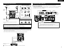
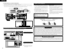
SETTING UP THE SYSTEM
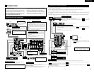
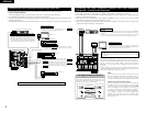
• Once all connections with other AV components have been completed as described in “CONNECTIONS”
(see pages 5 to 9), make the various settings described below on the monitor screen using the AVR-2805’s
on-screen display function.
These settings are required to set up the listening room’s AV system centered around the AVR-2805.
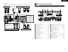
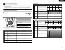
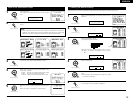
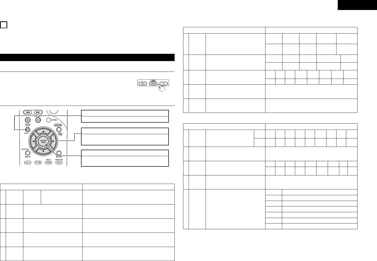
SYSTEM SETUP button
Press this to display the system setup menu.
ENTER button
Press this to switch the display.
Also use this button to complete the setting.
CURSOR buttons
Use these to move the cursors the left, right, up and
down on the screen.
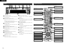
• System setup items and default values (set upon shipment from the factory)
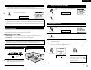
Use the following buttons to set up the system
• Use the following buttons to set up the system.
1
2
Check that the remote control unit set to AMP mode. (TAPE, CDR/MD, CD)
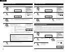
Auto Setup/Room EQ Default settings
Auto Setup
Manual EQ
Setup
Room EQ
Setup
Direct Mode
Setup
Mic Input
Select
Power Amp
Assignment
This parameter is for optimizing the Room EQ with
which the audio signals are produced from the
speakers.
Set the Room EQ setting with All or Assign for
each surround mode.
Set the ON/OFF setting of Room EQ, in the case of
the surround mode is in Direct or Pure Direct.
Set this to switch the Mic Input jack for use for Mic
or V.Aux L-channel input jack.
Set this to switch the surround
back channel’s power amplifier
for use for zone2.
SURROUND BACK
All Channel and Frequency=0 dB
All
OFF
Mic
1
2
3
4
5
1. Auto Setup/Room EQ
(Remote control unit)
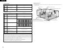
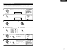
2. Speaker Setup
Speaker Setup Default settings
3
4
5
Speaker
Configuration
Channel
Level
Crossover
Frequency
Subwoofer
Mode
Input the combination of speakers in your
system and their corresponding sizes (SMALL for
regular speakers, LARGE for full-size, full-range) to
automatically set the composition of the signals
output from the speakers and the frequency
response.
This adjusts the volume of the signals output from
the speakers and subwoofer for the different
channels in order to obtain optimum effects.
Set the frequency (Hz) below which the bass so of
the various speaker is to be output from the
subwoofer.
This selects the subwoofer speaker for playing
deep bass signals.
Front Sp.
Large
Center Sp. Surround Sp.Subwoofer
Small SmallYes
Front L & R Center Surround L & RSubwoofer
3.6 m (12 ft) 3.6 m (12 ft) 3.0 m (10 ft)3.6 m (12 ft)
Front L
80Hz
LFE
Front R Center
Surround
R
Surround
Back R
Subwoofer
0 dB 0 dB 0 dB 0 dB 0 dB 0 dB
Surround Back
Sp.
Small / 2spkrs
2
Delay Time
This parameter is for optimizing the timing with
which the audio signals are produced from the
speakers and subwoofer according to the listening
position.
SBL & SBR
3.0 m (10 ft)
Surround
Back L
0 dB
Surround
L
0 dB
1
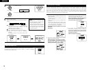
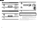
3. Input Setup
Input Setup Default settings
Digital In
Assignment
Ext. In
Subwoofer
Level
Component
In Assign
Video Input
Mode
Auto Tuner
Presets
This assigns the digital input jacks for the
different input sources.
Set the Ext. In Subwoofer terminal playback
level.
This assigns the color difference (component)
video input jacks for the different input sources.
Set the input signal to be output from the monitor
output terminal.
FM stations are received automatically and stored
in the memory.
Input
source
Digital
Inputs
CD DVD VDP TV DBS
CDR/
TAPE
COAX1 COAX2 OPT1 OFF OPT2 OPT4
Subwoofer = +15 dB
VCR-1
OPT3
V. AUX
OPT5
1
2
3
4
5
VCR-2
OFF
DVD
AUTO
VDP TV VCR-1 V. AUX
——
VIDEO
1
NONE
VIDEO
2
NONE NONE
——
VCR-2
NONE
DBS
VIDEO
3
A1 ~ A8
87.5/89.1/98.1/108.0/90.1/90.1/90.1/90.1 MHz
B1 ~ B8
522/603/999/1404/1611 kHz, 90.1/90.1/90.1 MHz
C1 ~ C8
90.1 MHz
D1 ~ D8 90.1 MHz
E1 ~ E8 90.1 MHz
F1 ~ F8 90.1 MHz
G1 ~ G8 90.1 MHz