28
<PRE1282>
En
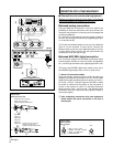
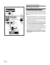
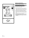
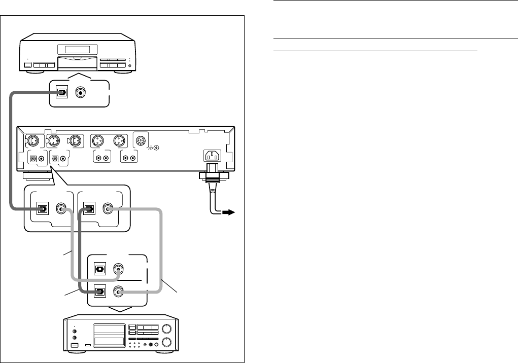
7 Digital signal connections.
(Before connecting this unit with other units please
remove the power connection to this unit.)
This unit features both optical and coaxial digital input and
output sockets, allowing flexibility for various connection
situations. The active input is selected from the front panel
switch, the outputs are both active, therefore either or both
can be used.
AConnect the digital input socket of the unit to the digital
output of the source device, such as a CD player. Use
either optical or coaxial connection. When making optical
connections, align the connector carefully with the socket
and insert fully into the socket.
BConnect either the optical or coaxial digital output socket
of the unit to the digital input of an external device such as,
a mixer, DAT or MD recorder. Never use both the optical
and coaxial connectors together to the same device, but
both outputs may be used to two different devices.
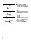
CFor coaxial digital connections use Phono/RCA type
connectors with 75 Ω cable for correct impedance. Avoid
the use of standard phono interconnection cables for
digital signals, as they are not usually of the correct
impedance and may cause signal degradation.
DAfter completing connections with other equipment
please ensure the power connection to the unit is
reconnected.
CONNECTION WITH OTHER EQUIPMENT
R L
LINE IN LINE OUT
DIGITAL IN
DIGITAL IN
OPTICALCOAXIAL
S/PDIF
AES
/EBU
OPTICAL
DIGITAL OUT
COAXIAL
S/PDIF
PUSH
PUSH
BALANCED IN BALANCED OUT
PUSH
DIGITAL
OPTICAL COAXIAL
OUTPUT
INPUT
OPTICAL
OUTPUT
COAXIAL
DIGITAL
RL
SIGNAL
GND
AC IN
PARALLEL
REMOTE
RL RL
DIGITAL IN
OPTICAL COAXIAL
S/PDIF
OPTICAL
DIGITAL OUT
COAXIAL
S/PDIF
A
B
C
CDR-850
D
C


