21
C4630 SE HOME AUDIO SYSTEM
Mounting the C4630 SE Keypads
NOTE: Do NOT mount the C4630 SE keypads in the same electrical box with AC house wiring,
light switches, or any other high-voltage device or control. The keypads can share gang boxes with
each other, or with other controls such as A/B speaker switches, infrared receivers and Volume
Controls, if these other devices are rated as Class 2 devices according to the National Electrical
Code.
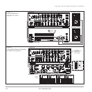
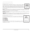
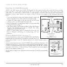
1. If you are using both a Main and Numeric Keypad, connect the
Numeric Keypad’s 14-pin ribbon cable between both keypads.
• Connect the ribbon cable so that the wire with the red stripe
connects to Pin 1 on both keypads (see
Figure 20
).
2. Mount the keypad(s) in an appropriate J-box or P-ring as described
in
Keypad Location
on page 19.
• The ribbon cable is long enough to allow a Main and Numeric
Keypad to be mounted side-by-side in a double J-box. Either
keypad can be mounted left or right.
NOTE: If the ribbon cable is connected incorrectly the
Numeric Keypad (including its backlighting) will not
function.
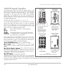
External Keypad Power
(see Figure 21)
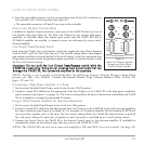
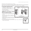
If you’re connecting 6 or fewer sets of C4630 SE Main and Numeric
Keypads (one set in each zone) to the C4630 SE, leave the Z
ONE 4 – 6
K
EYPAD POWER Switch in the INT (internal) position. No external keypad power is
required.
If you’re connecting more than 6 sets of C4630 SE Main and Numeric Keypads to the
C4630 SE, set the Z
ONE 4 – 6 KEYPAD POWER Switch to the EXT (external) position. Connect
a 12VDC 1A external power supply (Sonance PS2 Power Supply, part #91352, available
separately) to the Z
ONE 4 – 6 KEYPAD EXTERNAL POWER connection to provide adequate
power for the keypads in Zones 4 – 6.
See the table on page 46 for information about powering K1 and K2 programmable
keypads.
F1AL 12VDC
RS-232
12 VDC
1.0 A IN
ZONE 4-6
KEYPAD POWER
INT
EXT
–
+
F
1AL 12VD
C
12 VDC
1.
0
A I
N
Z
ONE 4-
6
K
EYPAD P
O
WER
INT
EXT
–
+
Figure 21:
Keypad External Power
Connection
C4630
MAIN
KEYPAD
RESERVED FOR NUMBERIC KEYPAD
PIN 14
PIN 1
•
1 2
C4630
NUMERIC
KEYPAD
CONNECTION TO MAIN KEYPAD
PIN 14
PIN 1
•
1 2
Red Stri
p
e to Pin 1
Ribbon Cable
Numeric Keypad Main Keypad
Figure 20:
Keypad Ribbon Cable


