


20
C4630 SE HOME AUDIO SYSTEM
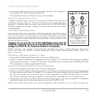
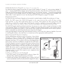
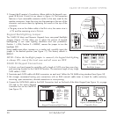
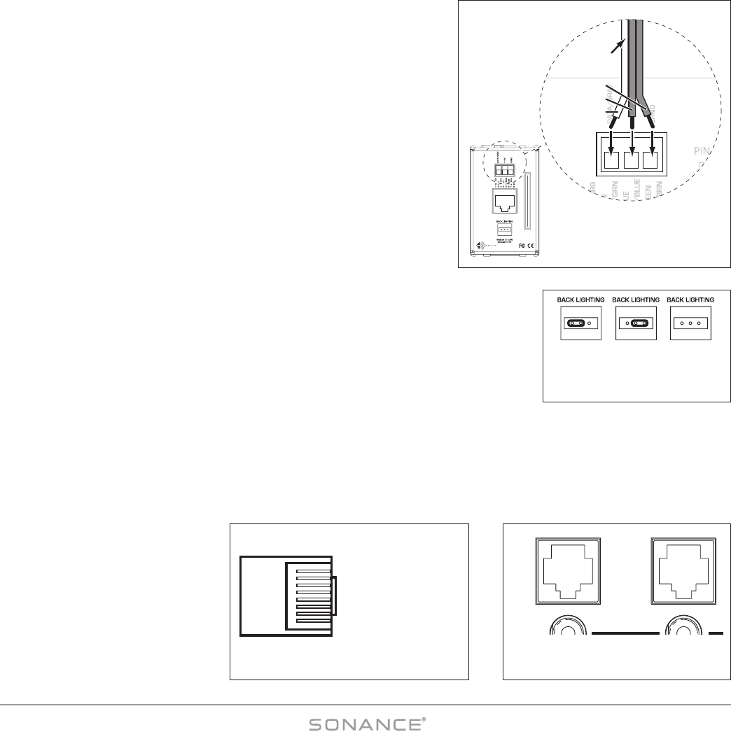
3. Connect the IR receiver’s 3-conductor ribbon cable to the keypad’s rear-
panel IR R
ECEIVER CONNECTION as shown in
Figure 16
. The connection
features a 3-pin removable connector similar to the ones used for the
speaker connectors. Insert the wires into the openings at the rear of the
connector and secure them by tightening the screws at the top of the
connector.
• The gray wire on the ribbon cable is the D
ATA wire, the center wire is
+12V and the remaining wire is G
ROUND
.
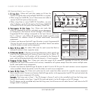
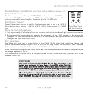
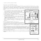
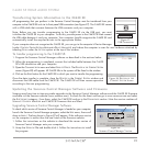
Keypad Backlighting Jumper
The C4630 SE Main and Numeric Keypads have rear-panel Backlight
Jumpers (
Figure 17
) that allow you to adjust the amount of keypad
backlighting to suit room lighting conditions and user preference.
Position 1 = DIM; Position 2 = BRIGHT; remove the jumper to turn the
backlight OFF.
Using needle-nose pliers, tweezers or a similar tool, carefully insert the
jumper in the desired position (see
Figure 17
). The factory default is
BRIGHT.
NOTE: Unless the backlight jumper is removed, the keypad backlighting
is always ON, even if the local zone and all zones are OFF.
C4630 SE Keypad Connections
1. In direct runs from keypad to controller, pull a length of CAT5 wire from every key-
pad mounting location to the C4630 SE location. The maximum length of any single
CAT5 cable is 1000’.
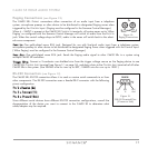
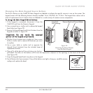
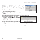
2. Terminate each CAT5 cable with RJ45 connectors on each end. Follow the TIA 568B wiring standard (see
Figure 18
).
3. We strongly recommend testing your connections with an RJ45 network cable tester to check for cable continuity,
miswiring, open connections, shorted connections or cross-pinning.
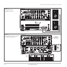
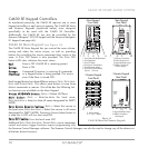
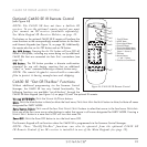
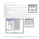
4. Connect the CAT5/RJ45 cable to the RJ45 Connection Jack on the back of the Main Keypad (see
Figure 14,
on page
18) and to the zone’s Keypad
Controller Port on the C4630 SE
(see
Figure 19
).
RJ45 Connector
(Flat Side UP)
TIA 568B
Wiring Standard
PIN
1
2
3
4
5
6
7
8
COLOR
White/Orange
Orange
White/Green
Blue
White/Blue
Green
White/Brown
Brown
SIGNAL
No Signal
No Signal
No Signal
IR Data
Status
No Signal
Ground
+12V DC
Figure 18:
Keypad Connection RJ45 Pinout
Z
O
N
E
1
Z
O
N
E
2
Figure 19:C4630 SE Keypad
Controller Ports
Figure 17: C4630 SE Keypad
Backlight Jumper
1 2 1 2 1 2
DIM OFFBRIGHT
C4630
MAIN
KEYPAD
RESERVED FOR NUMBERIC KEYPAD
PIN 14
PIN 1
•
1 2
IR DATA (white)
+12V (center)
GROUND
FROM IR
RECEIVER
Figure 16:
Connecting the IR Receiver
to the Keypad