


17
C4630 SE HOME AUDIO SYSTEM
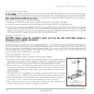
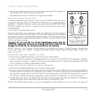
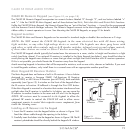
Paging Connections (see Figure 12)
The C4630 SE’s P
AGING connections allow connection of an audio input from a telephone
system, microphone preamp or other device to be distributed to designated Paging zones when
triggered by the C
ONTROL Input. (Paging must be configured in the Sonance Control Manager.)
When 6 – 24VDC is present at the C4630 SE C
ONTROL IN terminals, all system zones set to ‘Allow
Paging’ as configured with the Sonance Control Manager will switch to audio from the P
AGE IN
jack. When the control voltage drops to 0VDC, audio in the zones will switch back to the select-
ed source component.
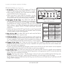
PP
AAGGEE
II
NN
::
One gold-plated mono RCA jack. Designed for use with line-level audio input from a telephone system,
microphone preamp or other device to be distributed to designated Paging Zones when triggered with the Control Input.
(‘Allow Paging’ must be configured in the Sonance Control Manager.)
PP
AAGGEE
OO
UUTT
::
One gold-plated mono RCA jack. Sends the Paging audio signal to other C4630 SEs in a system using
multiple C4630 SE controllers.
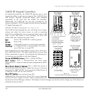
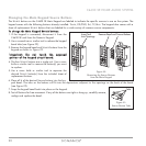
TTrriiggggeerr WWiirree::
Connect a 2-conductor non-shielded wire from the trigger voltage source on the Paging device to one
C4630 SE’s C
ONTROL INPUT terminal (see
Figure 11,
on page 16), and daisy-chain to the CONTROL INPUT terminals of all other
C4630 SEs in the system. (Use 20AWG wire for runs up to 500’; 18AWG wire for runs up to 1000’.)
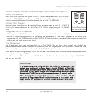
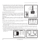
RS-232 Connection (see Figure 13)
The C4630 SE’s RS-232 connection allows it to send or receive serial commands to or from
other components. The RS-232 connection uses a female DB-9 connector with the following
pinout configuration:
PPiinn 22 == RReecceeiivvee ((RR
XX
))
PPiinn 33 == TTrraannssmmiitt ((TT
XX
))
PPiinn 55 == GGrroouunndd (( GG
NNDD
))
Since different serial devices have different RS-232 connection configurations, consult the
documentation of the device you want to connect to the C4630 SE to determine what
cable/adapter may be required.
IN OUT
PAGE
Figure 12:
Paging Connections
RS-232
Pin2
Rx
Pin3
Tx
Pin5
Gnd
Figure 13:
RS-232 Terminal Pins
(Connector Side)