


15
C4630 SE HOME AUDIO SYSTEM
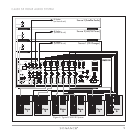
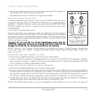
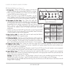
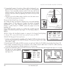
IR Connections (see Figure 9)
11.. IIRR LL
II NNKK
PPoorrtt::
3.5mm mini jack that creates an IR buss for
Common IR signals when using multiple C4630 SEs in a system.
• When using two C4630 SEs, use a 3.5mm mono mini cable to
connect the IR Link jacks on the two units.
• When using three or more C4630 SE Controllers, use mini
plug Y-adaptors on the IR Link jack on the Primary C4630 SE
to connect to the IR Link jacks of the Secondary C4630 SEs.
22.. PP
RR OO GG RR AAMMMM EEDD
IIRR OO
UUTT
PPoorrttss::
Four 3.5mm mini jacks that
output IR commands to the four individual source components
as configured in the Sonance Control Manager. (The default
Programmed IR Port settings correspond to the Input Source numbering:
Port 1 = Source 1, etc.) Allows IR signals to be routed to specific source
components, for selective control of multiple same-brand, same-model
components.
• Connect one Sonance OptiLinQ
®
-type IR emitter to each Programmed IR
Out port for each source component to be controlled. Attach one emitter
to the IR window on each source component.
33.. ZZ
OO NNEE
IIRR DD
AATTAA
LLEEDD::
Six amber LEDs (one for each zone) that flash to
indicate IR activity in their respective zones.
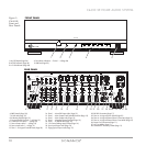
44.. IIRR RR
OO UUTTIINNGG
SSwwiittcchh::
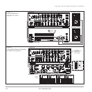
3-Position switch that determines which signals are
output by the Programmed and Common IR ports (see chart in
Figure 10
).
For most installations, the IR emitters will be connected to the Common IR
ports, with the IR Routing Switch left in the P
ROGRAMMED > COMMON position.
55.. CC
OO MMMM OONN
IIRR OO
UUTT
PPoorrttss::
Four 3.5mm mini jacks that output all IR commands regardless of zone for all source
components (all zones have control of all sources). Intended for all systems except those that contain multiple same-
brand, same-model source components.
• Connect one Sonance OptiLinQ-type IR emitter to each C
OMMON IR Out port for each common source component
to be controlled. Attach one emitter to the IR window on each source component.
66.. LL
OO CCAALL
IIRR OO
UUTT
PPoorrttss::
Six 3.5mm mini jacks (one for each zone) that allow control of a specific source component
from a specific zone. Connect one Sonance OptiLinQ-type emitter to the appropriate Local IR Out jack and attach the
emitter to the source component’s IR window.
EExxaammppllee::
The living room is Zone 1. The CD changer is Source 2 and is to be controlled
only
from the living room.
Connect the IR emitter to the Zone 1 Local IR Out jack and attach it to the IR window on the CD changer.
The CD changer can be controlled only from the living room, but all zones can still select Source 2 and listen to the CD
changer when it is playing.
Z
O
N
E
1
1
2
3
4
COMMON IR OUT
PROGRAMMED IR OUT
1
2
3
IR LINK
IR ROUTING
1 COM > PROG
2 OFF
3 PROG > COM
12
546
3
Figure 9: IR Connections
PROGRAMMED
IR PORT OUTPUT
COMMON
IR PORT OUTPUT
POSITION 1
COM > PROG
POSITION 3
PROG > COM
POSITION 2
OFF
Programmed IR
Signals
Common IR
Signals
Common IR
Signals
Common IR
Signals
Common IR
Signals
Programmed IR
Signals
Programmed IR
Signals
Programmed IR
Signals
Figure 10: IR Routing Switch Function