


TECHNICALLY SPEAKING
59
Balanced and Unbalanced
Analog Audio Connections
Recording and broadcast studios use balanced connec-
tions almost exclusively because of balanced lines’ inher-
ent ability to reject noise and hum, even when compo-
nents are far apart and connected by long cables.
Certain high-quality preamplifiers, amplifiers, and sur-
round controllers built for residential use include bal-
anced connections with XLR jacks for the same reasons.
The C 1’s balanced outputs enable you to take full
advantage of the inherent noise-rejection capability
and superior sound quality of Parasound Halo power
amplifiers, especially when the amplifiers are mount-
ed far away, near the speakers. The balanced input on
the C 1 also ensures the best possible analog connec-
tion to a source component having balanced output.
And, for the purest possible sound, the C 1 has a
Bypass mode that feeds the balanced audio input
signal directly to the front left and right balanced
outputs, with no processing except volume control.
The balanced jacks on the C 1 are wired according to
the AES standard (shield on pin 1, positive on pin 2,
return on pin 3). Should it ever be necessary for some
reason to connect any of the C 1’s balanced jacks to
unbalanced jacks on another component, you can
make an adapter cable by wiring an unbalanced
cable’s shield to pin 1 on an XLR connector, wiring
the unbalanced cable’s center conductor to pin 2,
and leaving pin 3 unconnected.
Unbalanced connections with RCA jacks are found on all
home audio equipment. RCA jacks and two-conductor
wires are less costly than the additional circuitry, higher
priced XLR connectors and three-conductor wiring
required for balanced connections. In an unbalanced line,
the positive audio signal appears at the center pin of
the RCA jack and the negative signal on the outer shield
wire, which also functions as the ground connection.
Unbalanced interconnect cables are vulnerable to hum
from an AC line, or other noise, such as RFI (Radio
Frequency Interference), which can be reproduced
through your loudspeakers. Since the unbalanced line’s
ground also carries the audio signal, there is no way for
the connected amplifier or preamplifier to distinguish
between the audio signals you want and unwanted
noise emanating from external sources.
In balanced lines, the positive and negative audio
signals are carried on separate conductors within a
separately grounded shield that provides equal inter-
ference-protection to each signal. The positive and
negative audio each have opposite polarity with
respect to ground, making them equal but 180° out
of phase with each other. The input uses differential
circuitry, which amplifies only the difference between
the audio signals but not the elements they have in
common. For example, when a 1-volt signal arrives at
a balanced input stage, the differential input “sees” a
positive 1 volt minus a negative 1 volt, or 2 volts total.
Any external hum and noise that somehow does get
into a balanced line appears on both conductors but
with opposite polarities. As a result, the input circuit
simply cancels the noise out, a process known as
common-mode rejection. One of the most important
specifications for a differential circuit is its ability to
reject signals common to both conductors. This is
measured in dB and is called the common mode
rejection ratio or CMRR.
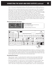
The Tape Monitor and its Many Uses
The Tape Monitor Play/In and Rec/Out jacks on the
C 1 are designed for easy integration of a stereo ana-
log recorder (tape, CD, MiniDisc, or even the inputs
and outputs of your computer’s sound card). It is espe-
cially useful with recorders that permit simultaneous
playback of the just-recorded tape, enabling you to
quickly compare the recorded output to the signal
you’re recording, simply by pressing the “Tape” key
on Page One of the Master remote’s C1/C2 menu.
The Tape Monitor jacks can also be used with equaliz-
ers and other two-channel signal processors. If you
connect the Rec/Out jack to the processor’s input,
and connect the processor’s output to the Play/In
jacks, you will be able to switch between the direct
output of the C 1 and the output of the processor.
If you have so many components that you’re short
of input jacks, the Play/In jack can also be used as an
extra unbalanced analog stereo input. However, the
signal from this input will not be available through
any of the recording outputs or Zone.
Bass and Treble Controls
The bass and treble controls offer adjustment of overall
tonal balance in the front left, center, and right channels.
The Bass controls allow you to boost or cut low frequen-
cies ±12 dB at 20 Hz, in 1-dB increments. The Treble
controls allow you to boost or cut high frequencies ±12
dB at 20 kHz in 1-dB increments. To preserve sonic
clarity, use these controls sparingly and only for record-
ings that actually sound better with tonal correction. You
will find that very slight adjustments can add a degree
of warmth, richness, clarity and airiness. However,
greater adjustments may obscure musical detail, and
even risk overloading your speakers. You can only adjust
the bass and treble controls via Page 3 of the C1/C2
menu on the Master remote.
Bass and treble controls do not affect the Rec/Out,
Record 1, Record 2, or Zone outputs, but their effect can
be heard when playing back through the Play/In input.
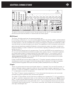
IR Repeater Input Jacks
The IR inputs (one for each zone) on the rear panel of