


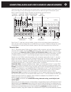
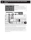
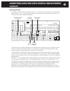
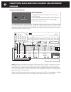
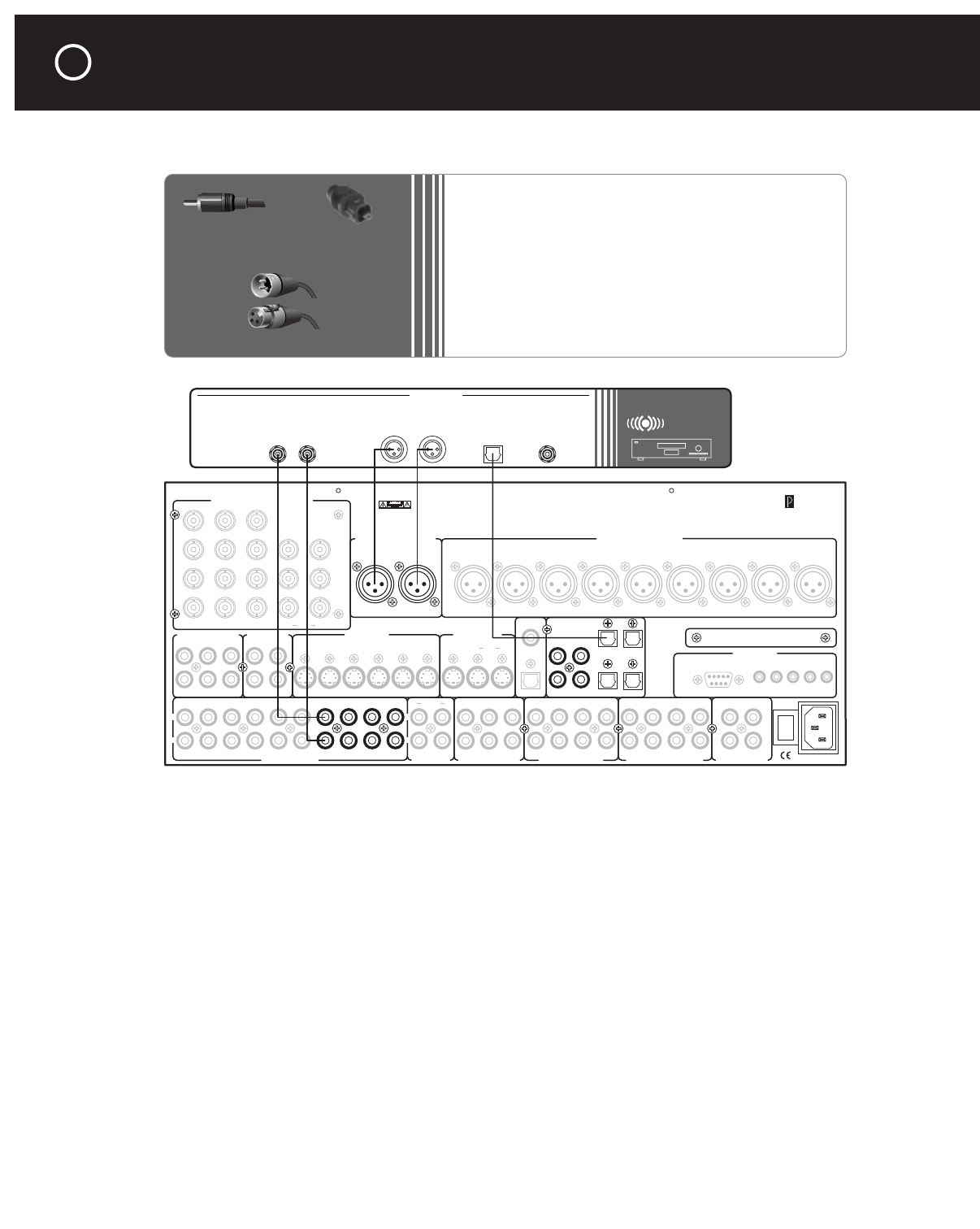
Connecting a Balanced-Output Audio Source
Normally, all balanced and unbalanced input signals appear at both the balanced and the unbal-
anced outputs of the C 1, including its Record, and Programmable outputs, but only signals
going to the main 7.1-channel outputs are affected by whatever surround, tone-control, and other
DSP (digital signal processor) settings you select.
There is a Bypass mode which sends signals directly from the left and right balanced inputs
to the left front and right front balanced output jacks, avoiding the DSP section, for additional
assurance of the signal’s purity (see the “Source Setup” in the chapter on “Adjustments,
Menus, and Setup”). In Bypass mode, signals from the balanced outputs are not available at
the recording or Zone outputs; if the balanced source also has unbalanced outputs, connecting
them as well will make its signal available for recording or remote-zone listening.
Bypass only affects the balanced outputs, so its benefits are only available with amplifiers that
accept balanced signals.
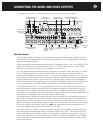
Audio 1 Audio 2
Audio 3 Audio 4
Front Surround Center
Sub
Back
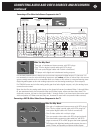
Balanced Analog Audio OutputsBalanced Analog Audio Inputs
C2 Controller
Parasound Products, Inc.
San Francisco, California, USA
Input 1
Input 2
Input 3
Output
Component Video Inputs and Outputs
Sync
Red
Green
Blue
H
V
Pr Y Pb
Composite Video Inputs Video Outputs
S-Video Inputs
Video 1 Video 2 Video 3 Video 4 Video 5 Video 6
S-Video Outputs
Record
Main
Digital Out
Coax
Digital Audio Inputs
Optical
Optical 2
Optical 1
Optical 4
Optical 3
Coax 1
Coax 2
Coax 3
Coax 4
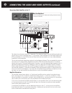
Made In
Finland
Expansion Port For
Future Technologies
IR Inputs – 12V Triggers –
RS-232 Control
External Control
L
R
L
R
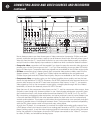
Analog Audio Inputs Tape Monitor Analog Audio Outputs Programmable OutMain Analog Audio Outputs7.1 Analog Audio Inputs
1
0
AC Power
CAUTION
TO PREVENT ELECTRIC SHOCK,
DO NOT REMOVE COVER. NO USER
SERVICEABLE PARTS INSIDE,
REFER SERVICING TO QUALIFIED
SERVICE PERSONNEL.
Left
Right
Left
Right
Center
Subwoofer
Left Surround
Right Surround
Left Back
Right Back
Pro 1
Record 1 Record 2 ZoneAudio 5
Play/In Rec/Out
Pro 3
Pro 1
Pro 4
Pro 2
Sub
Front Surround Center
Back
Digital Out
Optical
Main Zone P1 P2 On-Off
Record
OSD
Zone
NoOSDMain
OSD No OSD
Video 1
Video 2
Video 3
Video 4
Video 5
Video 6
Video 1 Video 2
Video 3 Video 4
Video 5 Video 6
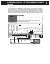
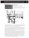
CD PLAYER
OUTPUTS
Digital
Optical
Output
Digital
Coaxial
Output
Unbalanced
Analog Audio
Balanced
Analog Audio
LR L R
RCA Plug
XLR Connectors
Male
Female
Toslink Connector
CONNECTING AUDIO AND VIDEO SOURCES AND RECORDERS
continued
42
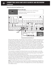
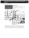
What You May Need:
•
Two balanced interconnects with XLR plugs
•
One optical digital cable with Toslink connectors
(or: one 75-ohm digital coaxial cable with RCA plugs)
•
Audio source component with balanced and unbal-
anced analog audio outputs and optical or coaxial
digital output.