


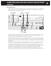
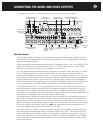
The output jacks of the C 1 are grouped with the input jacks of the same types:
Main Audio Outputs
All audio input signals, whether from unbalanced analog, balanced analog, or digital sources
are available at the unbalanced and balanced analog outputs, but only digital input signals also
appear at the digital outputs.
Digital input signals are passed straight through to the digital outputs, with no processing. That
means that signals from the digital outputs of the C 1 will not be heard in surround unless
decoded or processed by some other component, down the line.
The main balanced and unbalanced analog outputs are in groups of eight jacks each, to handle
up to 7.1-channel signals from multichannel sources or from stereo sources processed to
include surround-channel ambience by the C 1. (The ninth balanced output jack, Pro 1, is a pro-
grammable output that will be covered later in this chapter, together with the four unbalanced
programmable output jacks.) If you choose not to process them, stereo signals will appear at
the left and right front output jacks, and mono signals will appear at the center-channel jacks (or,
if your setup includes no center speaker, through the same left and right front outputs).
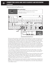
If the cable between the C 1 and your amplifiers is more than about 10 feet (3 meters) long,
using the balanced outputs (and amplifiers with balanced inputs) will guard against hum and
noise pickup in the cables. With balanced connections, it’s feasible to mount your amplifiers
very close to your speakers and use short speaker cables. With some amplifiers (especially tube
amps) and some speakers, this can subtly improve performance.
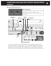
The balanced and unbalanced outputs normally carry the signals from the balanced input and
the unbalanced inputs. You can select a Bypass mode (see “Source Setup” in the chapter on
“Adjustments, Menus, and Setup”) to route the balanced input signal directly to the left and
right front balanced output jacks, passing through no circuitry except the analog volume control.
Should you wish to use Bypass mode, you must use balanced connections between the C 1
and the amplifiers serving the right and left front channels.
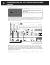
The other amplifiers, however, can be connected via balanced or unbalanced cables. We sug-
gest using amps with balanced inputs in locations farthest from the C 1 and amps with only
unbalanced inputs nearby. While it’s best to use identical amplifiers for all channels, it’s some-
times more convenient or economical to use a mixture of amplifiers, especially if you already
have some. (See “Using Unmatched Amplifiers,” in the “Technically Speaking” section at the
back of this manual.)
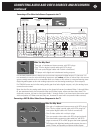
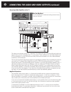
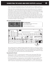
Left
Right
Center
Subwoofer
Left Surround
Right Surround
Left Back
Right Back
Pro 1
Balanced Analog Audio OutputsBalanced Analog Audio Inputs
Left
Right
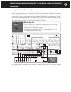
C2 Controller
Parasound Products, Inc.
San Francisco, California, USA
Input 1
Input 2
Input 3
Output
Component Video Inputs and Outputs
Sync
Red
Green
Blue
H
V
Pr Y Pb
Composite Video Inputs
Video 1
Video 2
Video 3
Video 4
Video 5
Video 6
Video Outputs
Record
OSD
Zone
NoOSDMain
S-Video Inputs
Video 1 Video 2 Video 3 Video 4 Video 5 Video 6
S-Video Outputs
Record
OSD No OSD
Main
Digital Out
Coax
Digital Audio Inputs
Optical
Optical 2
Optical 1
Optical 4
Optical 3
Coax 1
Coax 2
Coax 3
Coax 4
Made In
Finland
Expansion Port For
Future Technologies
Main Zone
IR Inputs – 12V Triggers –
P1 P2 On-OffRS-232 Control
RS-232 Control
External Control
L
R
L
R
Video 1
Video 2
Video 3 Video 4
Video 5 Video 6
Audio 1 Audio 2
Audio 3 Audio 4
Audio 5
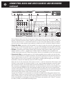
Analog Audio Inputs Tape Monitor
Record 1 Record 2 Zone
Analog Audio Outputs
Play/In Rec/Out
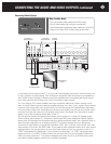
Programmable Out
Pro 3
Pro 1
Pro 4
Pro 2
Main Analog Audio Outputs
Sub
Front Surround Center
Back
7.1 Analog Audio Inputs
Front Surround Center
Sub
Back
1
0
AC Power
CAUTION
TO PREVENT ELECTRIC SHOCK,
DO NOT REMOVE COVER. NO USER
SERVICEABLE PARTS INSIDE,
REFER SERVICING TO QUALIFIED
SERVICE PERSONNEL.
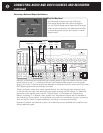
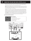
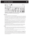
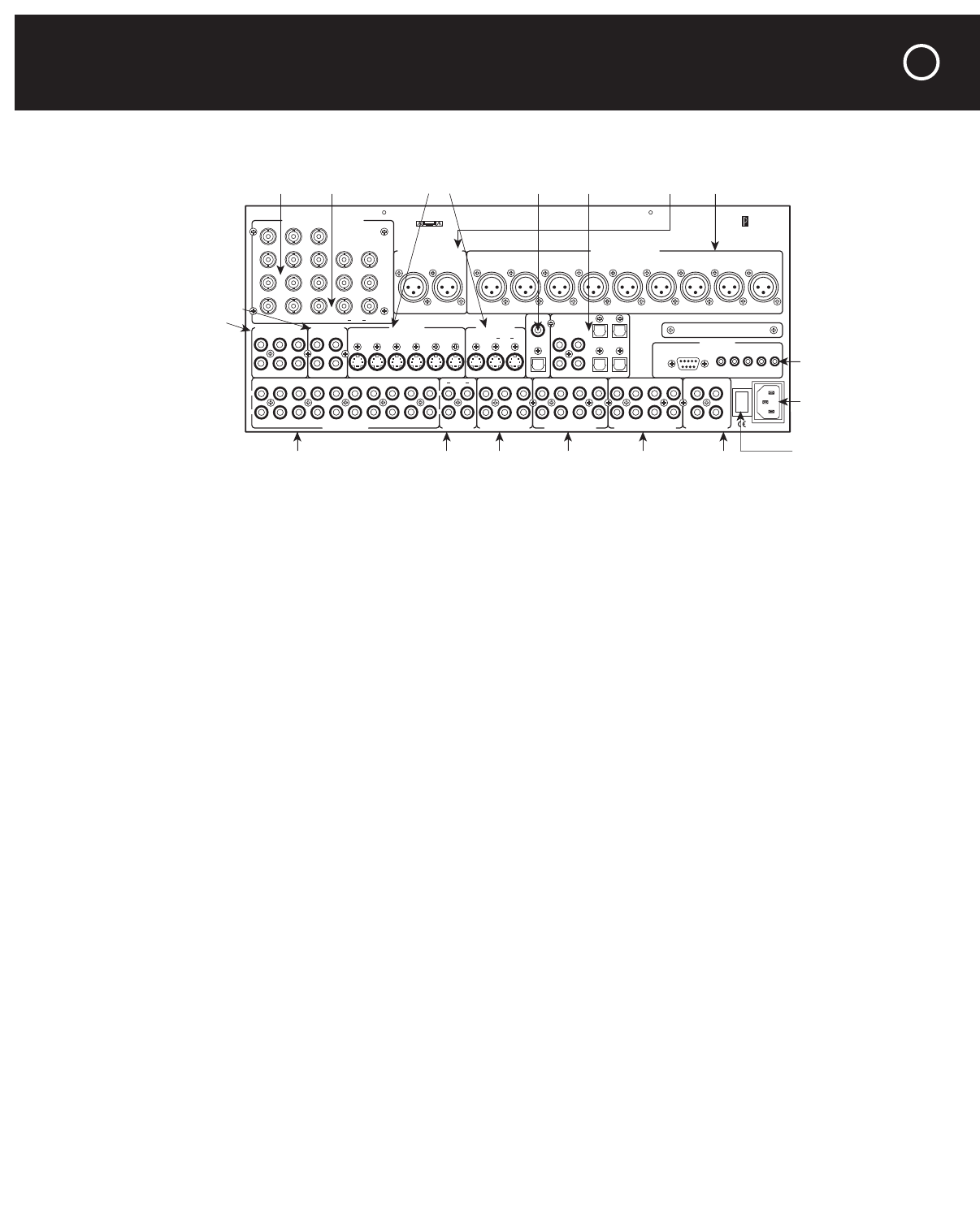
Balanced Analog Audio
Inputs & Outputs
Unbalanced Analog
Audio Inputs
Composite
V
ideo Outputs
& Inputs
Tape
Monitor
Input &
Outputs
Component Video
Inputs & Outputs
Zone &
Record
Outputs
7.1 Channel
Analog Inputs
Main Analog
Outputs
Programmable
Outputs
S-Video
Inputs & Outputs
Digital Audio
Outputs & Inputs
Control
Jacks
AC Cord
Inlet
AC Power
Switch
CONNECTING THE AUDIO AND VIDEO OUTPUTS
47