


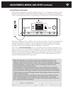
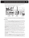
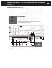
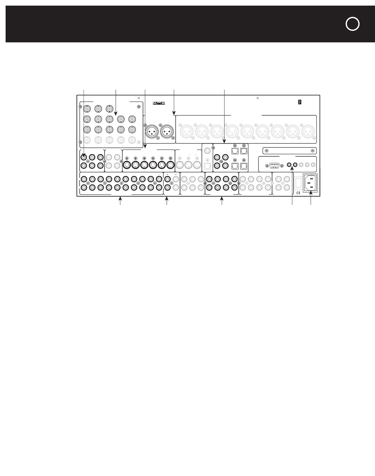
There are more than 100 signal input and output jacks on the Halo processor’s rear panel–more
than you’re likely to use, but enough to ensure you can make any type of connection you’re
likely to need. To simplify things, the jacks are grouped by type and function:
Even if your C 1 was set up by an installer, it pays to know a bit about these connections in
case you ever need to change them or trouble-shoot your system. (Cables and plugs can cause
more problems in audio and home theater systems than the components they connect do.)
Connection Types
The C 1 has three types of video and four types of audio connector, and your other components
may use some of each. The three video connection types, each of which uses a different type
of connector, are Composite video, S-Video, and Component video, listed in order of increas-
ing picture quality. For connections between video sources (such as VCRs, DVD players, and TV
or satellite tuners) and the C 1, use the highest-quality output connection that source offers.
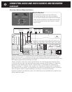
Signals from the S-Video inputs also appear at the composite output jacks of the C 1, but com-
posite input signals appear only at the composite output jacks. Component-video input signals
appear only at the component-video output jacks, respectively. So, to ensure that all video
sources can be seen, use both composite and S-Video connections (and component video, too,
if available) between the C 1 and your TV, video monitor, or projector.
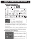
Composite video connections (labeled simply “Video” on the rear panel of the C 1) uses “RCA”
jacks, yellow-coded to distinguish them from the RCA jacks provided for analog and digital audio.
S-Video connections use multi-pin plugs and jacks that must be oriented identically in order to fit
together. This orientation is not standardized (the S-Video jacks on the C 1 are oriented as shown
on the rear-panel diagrams). Since S-Video cables are thick and hard to twist, it pays to look at
the end of the plug to line up its pins with the holes in the jack before trying to insert it.
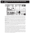
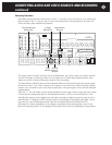
Component video connections use three cables (or five, for certain equipment which has sepa-
rate synchronization jacks); The component-video jacks on the C 1 are the professional, BNC type,
whose connectors lock firmly together when twisted, but adapters are provided for use with
cables having the more common RCA plugs.
The four audio connections are unbalanced analog, balanced analog, coaxial digital, and
optical digital.
Most analog sources (such as tuners, and tape decks), and the analog outputs of CD players and other
digital sources, have unbalanced output circuits with one RCA jack per channel. The channels are fre-
quently color-coded, usually red for the right stereo or right front channel and black or white for the left
or left front. If your best analog source or your amplifiers have balanced connections (usually via
three-pin XLR jacks), using them instead of the unbalanced RCA jacks will provide additional protection
Balanced Analog Audio OutputsBalanced Analog Audio Inputs
Left
Right
C2 Controller
Parasound Products, Inc.
San Francisco, California, USA
Input 1
Input 2
Input 3
Output
Component Video Inputs and Outputs
Sync
Red
Green
Blue
H
V
Pr Y Pb
Composite Video Inputs
Video 1
Video 2
Video 3
Video 4
Video 5
Video 6
Video Outputs
Record
OSD
Zone
NoOSDMain
S-Video Inputs
Video 1 Video 2 Video 3 Video 4 Video 5 Video 6
S-Video Outputs
Record
OSD No OSD
Main
Digital Out
Coax
Digital Audio Inputs
Optical
Optical 2
Optical 1
Optical 4
Optical 3
Coax 1
Coax 2
Coax 3
Coax 4
Made In
Finland
Expansion Port For
Future Technologies
Main Zone
IR Inputs – 12V Triggers –
P1 P2 On-OffRS-232 Control
RS-232 Control
External Control
L
R
L
R
Video 1
Video 2
Video 3 Video 4
Video 5 Video 6
Audio 1 Audio 2
Audio 3 Audio 4
Audio 5
Analog Audio Inputs Tape Monitor
Play/In Rec/Out
Programmable Out
Pro 3
Pro 1
Pro 4
Pro 2
7.1 Analog Audio Inputs
Front Surround Center
Sub
Back
AC Power
CAUTION
TO PREVENT ELECTRIC SHOCK,
DO NOT REMOVE COVER. NO USER
SERVICEABLE PARTS INSIDE,
REFER SERVICING TO QUALIFIED
SERVICE PERSONNEL.
Left
Right
Center
Subwoofer
Left Surround
Right Surround
Left Back
Right Back
Pro 1
Main Analog Audio Outputs
Sub
Front Surround Center
Back
Record 1 Record 2 Zone
Analog Audio Outputs
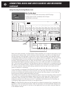
1
0
Component
Video Inputs
Balanced Analog
Audio Inputs
Unbalanced Analog
Audio Inputs
Tape Monitor
Input
Composite
Video Inputs
7.1 Channel
Analog Inputs
S-Video
Inputs
Digital
Audio Inputs
AC Cord
Inlet
IR
Inputs
CONNECTING AUDIO AND VIDEO SOURCES AND RECORDERS
37