


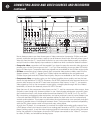
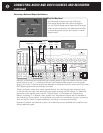
against hum and other noises, especially if your equipment rack is crowded with other components or
your cables are more than 10 feet (3 meters) long. (For more information, refer to the “Balanced and
Unbalanced Lines” section in the “Technically Speaking” section toward the end of this manual.)
Balanced and unbalanced input signals normally appear at both the balanced and unbalanced outputs
(including the recording outputs). However, in Bypass mode (see the chapter on “Adjustments,
Menus, and Setup”), when the balanced input is selected its signal passes straight to the front left
and front right balanced outputs, and unbalanced signals go only to the unbalanced outputs. Signals
from balanced or unbalanced analog sources do not appear at the digital outputs of the C 1.
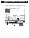
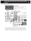
For best playback performance from digital sources (such as CD, DVD, and DAT players or
recorders), connect them to the digital inputs of the C 1. It usually makes little difference whether
you use coaxial connections (black RCA jacks on the C 1) or optical connections (small square
Toslink connectors); however, if the cables must make sharp bends, optical cables should not be
used. Signals from the digital inputs also pass through the 24-bit digital-to-analog converters in the
C 1 to appear at its main analog outputs. When Toslink jacks are not in use, they should be protect-
ed from dust with the small black plastic plugs supplied.
Note: Although analog audio cables have the same plugs as coaxial digital cables, they do not
have the proper characteristics to transfer digital signals properly. However, composite-video
cables (which usually have yellow plugs) can be used.
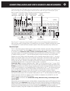
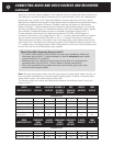
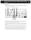
The following table summarizes the relationships between the different types of input and
output in the C 1:
Note: Programmable Outputs can access the same sources as the Main Outputs.
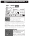
General Rules When Connecting Sources to the C 1:
•
To avoid sudden blasts of noise (which can harm your speakers), make sure
the power cord of the C 1 is disconnected, or that its rear-panel power switch
is turned off (the “0” position).
•
Make sure all your cables are long enough so that they are not strained or
stretched when you pull the C 1 out to make or change connections.
•
Don’t use excessively long cables; they cost more money, get in your way,
and can reduce signal quality.
CONNECTING AUDIO AND VIDEO SOURCES AND RECORDERS
continued
38
Unbalanced Analog In Yes Yes Yes Yes No Yes
Balanced In – Normal Yes Yes Yes Yes No Yes
Balanced In – Bypass No Yes No No No No
Tape Monitor Play/In Yes Yes No No No No
Digital Inputs Yes Yes No No Yes No
7.1-Channel
Analog Inputs Yes Yes Yes Yes No No
AUDIO MAIN BALANCED RECORD 1 & TAPE DIGITAL ZONE
INPUTS/OUTPUTS OUTPUTS OUTPUTS RECORD 2 MONITOR OUTPUTS OUTPUT
OUTPUTS REC/OUT
Available From
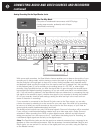
Composite Video In Yes No No Yes No Yes
S-video In Yes Yes No No Yes No
Component Video In No No Yes No No No
VIDEO COMPOSITE S-VIDEO
COMPONENT COMPOSITE
S-VIDEO ZONE
INPUTS/OUTPUTS VIDEO OUTPUTS VIDEO VIDEO REC/OUT OUTPUT
OUTPUTS OUTPUT REC/OUT
Available From