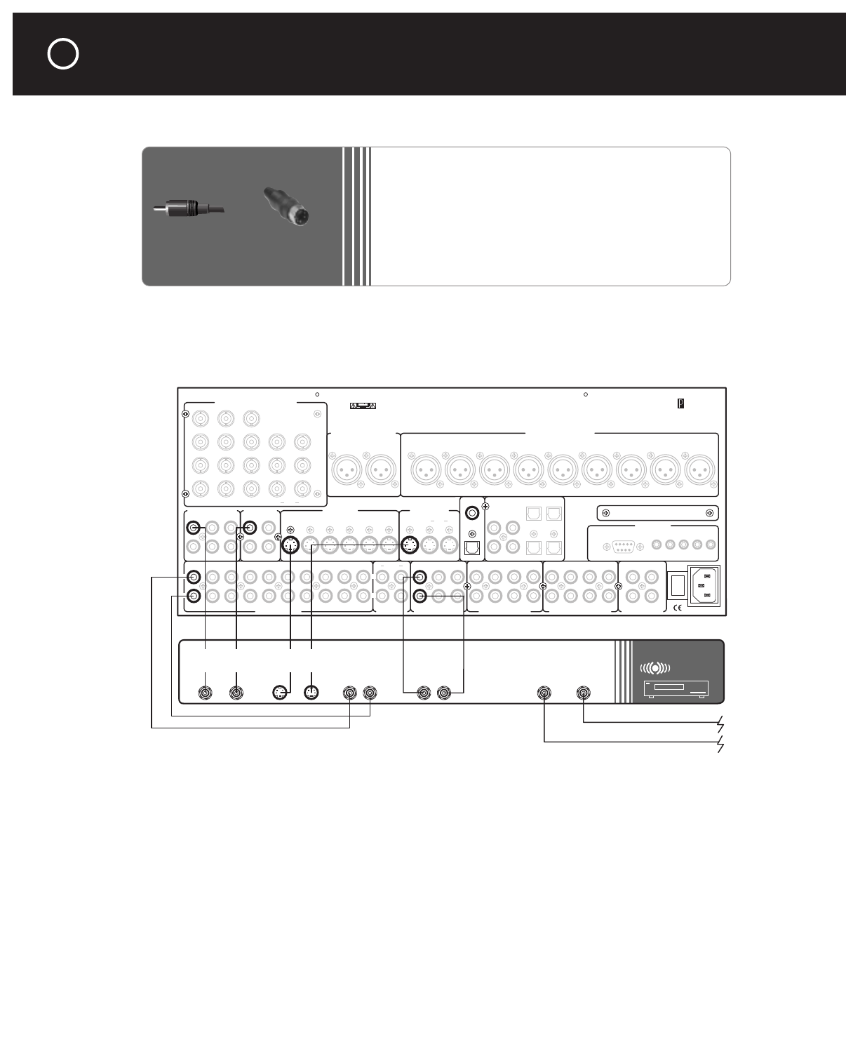
Connecting a Video Recorder
The video Record jacks, and the Record 1 and Record 2 audio output jacks, carry the same signal
as the other main-zone outputs. To tape one video or broadcast while you view another, connect
your video recorder to the Zone video and audio output jacks and use the Zone control mode to
select the source you want to record.
(
Note: Video signals can also be recorded via the video monitor outputs. However, do not use
the “OSD” jacks, or the on-screen display will be superimposed forever on your recording.)
(A third option, of course, is to record broadcast, cable, or satellite program through the video
recorder’s antenna/cable [RF] inputs; this can be done regardless of what you’re watching, and
even when the C 1 is turned off.)
Cabling for a DVD recorder would be similar to that shown for a VCR, with the addition of digital
audio connections like those shown for a digital audio recorder earlier in this chapter.
Video 1
Video 2
Video 3
Video 4
Video 5
Video 6
Video 1 Video 2
Video 3 Video 4
Video 5 Video 6
Audio 1 Audio 2
Audio 3 Audio 4
Record 1 Record 2 ZoneAudio 5
Play/In Rec/Out
Record
OSD
Zone
NoOSDMain
Digital Out
Optical
Optical 1
Optical 3
Coax 1
Coax 2
Coax 3
Coax 4
Optical 2
Optical 4
OSD No OSD
Front Surround Center
Sub
Back
Balanced Analog Audio OutputsBalanced Analog Audio Inputs
C2 Controller
Parasound Products, Inc.
San Francisco, California, USA
Input 1
Input 2
Input 3
Output
Component Video Inputs and Outputs
Sync
Red
Green
Blue
H
V
Pr Y Pb
Composite Video Inputs Video Outputs
S-Video Inputs
Video 1 Video 2 Video 3 Video 4 Video 5 Video 6
S-Video Outputs
Record
Main
Coax
Digital Audio Inputs
Made In
Finland
Expansion Port For
Future Technologies
IR Inputs – 12V Triggers –
RS-232 Control
External Control
L
R
L
R
Analog Audio Inputs Tape Monitor Analog Audio Outputs Programmable OutMain Analog Audio Outputs7.1 Analog Audio Inputs
1
0
AC Power
CAUTION
TO PREVENT ELECTRIC SHOCK,
DO NOT REMOVE COVER. NO USER
SERVICEABLE PARTS INSIDE,
REFER SERVICING TO QUALIFIED
SERVICE PERSONNEL.
Left
Right
Left
Right
Center
Subwoofer
Left Surround
Right Surround
Left Back
Right Back
Pro 1
Pro 3
Pro 1
Pro 4
Pro 2
Sub
Front Surround Center
Back
Main Zone P1 P2 On-Off
VCR
Audio
Outputs
Video
Output Input
S-Video
Output Input
Audio
Inputs
To Cable,
Antenna or
Set-top Box
To
TV
LR
LR
RCA Plug
S-Video Connector
CONNECTING AUDIO AND VIDEO SOURCES AND RECORDERS
continued
46
What You May Need:
•
Two pairs of unbalanced analog audio interconnects,
with RCA plugs
•
Two composite video interconnects, with RCA plugs
•
Two S-video interconnects, with multi-pin plugs
•
VCR or other video recorder


