


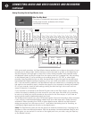
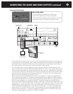
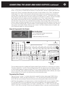
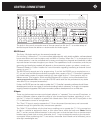
The C 1 allows you to feed separate audio or audio-video programs to two different areas, or
zones, in your home. To feed video and audio to a second zone, connect a video cable with RCA
plugs to the “Zone” composite video jack and a pair of audio cables to the “Zone” unbalanced-
output jacks. The “Zone” audio output is always stereo (unless you are playing a monophonic
source). When you select a source for this output, the display on the C 1 will initially show what-
ever listening mode that source was last used with but will revert to “Stereo” almost immediate-
ly. Remember that only analog sources are available at the “Zone” audio output jacks.
We strongly recommend that you use a professional installer when setting up a second enter-
tainment zone. The pros are very experienced at snaking wires through walls, know just what
kinds of cable will keep long cable runs from diminishing audio and video quality, and save you a
lot of work and potential grief. A good installer can also suggest ways to enhance your second-
zone system and make it better suited to your needs. If you don’t already have an installer, ask
your Parasound dealer for recommendations.
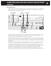
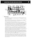
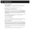
Using the Programmable (Aux) Outputs:
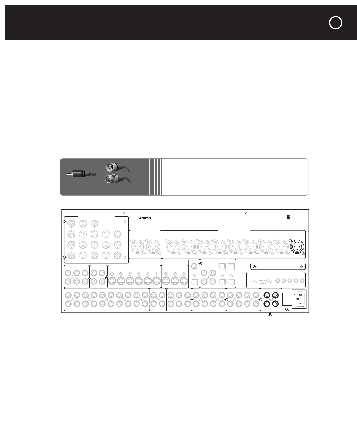
The one balanced and four unbalanced Programmable Outputs enable you to enhance your system.
The jacks marked Pro 1 and Pro 3 (Aux Channels 9 and 10 in the setup menu) can address acoustics
or room shape problems or add new effects. The Pro 2 output duplicates the main subwoofer chan-
nel; Pro 4 is similar, with a 20-Hz low-pass filter, to feed tactile transducers (floor shakers); the output
level and delay for Pro 2 and 4 is the same as the main subwoofer output.
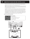
Programming New Channels
Here are some “recipes” to create channels for special functions (see pages 29-30). We’ve
abbreviated left, center, and right channels as L, C, R; left and right surround side channels
as LS, RS; the surround back channel as B; and the low-frequency effects channel as LFE.
•
Add Extra side speakers: A simple recipe is to feed the additional left surround speaker 100%
LS, and feed 100% RS to the additional right surround speaker. If the added speakers are
toward the front of the seating area, you might try blending 10% L + 90% LS on the left side,
10% R + 90% RS on the right. Extra surround speakers closer to the rear could blend signals
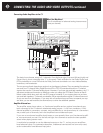
Record
OSD
Zone
NoOSDMain
Record 1 Record 2 Zone
Main Zone
Pro 3
Pro 1
Pro 4
Pro 2
Programmable
Outputs
Optical 1
Optical 3
Coax 1
Coax 2
Coax 3
Coax 4
Optical 2
Optical 4
Video 1 Video 2
Video 3 Video 4
Video 5 Video 6
Audio 1 Audio 2
Audio 3 Audio 4
Balanced Analog Audio OutputsBalanced Analog Audio Inputs
C2 Controller
Parasound Products, Inc.
San Francisco, California, USA
Input 1
Input 2
Input 3
Output
Component Video Inputs and Outputs
Sync
Red
Green
Blue
H
V
Pr Y Pb
Composite Video Inputs Video Outputs
S-Video Inputs
Video 1 Video 2 Video 3 Video 4 Video 5 Video 6
S-Video Outputs
Record
Main
Digital Out
Coax
Digital Audio Inputs
Optical
Made In
Finland
Expansion Port For
Future Technologies
IR Inputs – 12V Triggers –
RS-232 Control
External Control
L
R
L
R
Analog Audio Inputs Tape Monitor Analog Audio Outputs Programmable OutMain Analog Audio Outputs7.1 Analog Audio Inputs
1
0
AC Power
CAUTION
TO PREVENT ELECTRIC SHOCK,
DO NOT REMOVE COVER. NO USER
SERVICEABLE PARTS INSIDE,
REFER SERVICING TO QUALIFIED
SERVICE PERSONNEL.
Left
Right
Left
Right
Center
Subwoofer
Left Surround
Right Surround
Left Back
Right Back
Pro 1
Video 1
Video 2
Video 3
Video 4
Video 5
Video 6
Sub
Front Surround Center
Back
Front Surround Center
Sub
Back
Digital Out
Optical
P1 P2 On-Off
Audio 5
Play/In Rec/Out
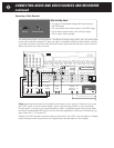
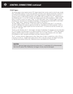
RCA Plug
XLR Connectors
Male
Female
CONNECTING THE AUDIO AND VIDEO OUTPUTS continued
51
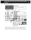
What You May Need:
•
1 to 4 unbalanced analog interconnects
(one per channel used)
•
1 balanced analog interconnect