


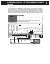
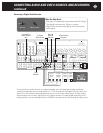
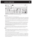

Connecting Video Displays
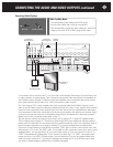
It may seem odd to connect the C 1 to your main video display three ways, as shown here, but
in many systems it makes sense. This is because composite video sources are not available at
the S-Video outputs (though S-Video sources are available at the composite jacks) and compo-
nent video sources can be seen only via the component video outputs.
So, if you have a VCR, which probably has both composite video and S-Video outputs, you’d
want to use S-Video to get the clearest possible pictures from that. If your system also includes
a source with component video outputs (the only kind that works for high-definition television),
only component video links would give you all the picture quality that source can provide. And if
you have a source that has only a composite video output, the signal from that source would
appear only at the composite video jacks of the C 1.
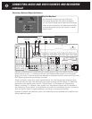
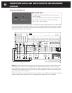
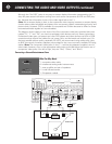
You can see the function and setup menus when you’re near the C 1’s built-in 5" display screen.
This is a handy way to adjust C 1 functions or go through DVD menu selections without superim-
posing a lot of information on the screen that your guests and family watch. You might also wish to
view on-screen information on a second, auxiliary TV or monitor located near your equipment.
Connect it to the S-Video or (more likely) composite “OSD” jack, as shown, and connect your main
video screen or TV to the “No OSD” jacks. If you prefer to view on-screen menus from your normal
seating position, you can see them on your main video screen or TV if you connect it to the C 1’s
“OSD” composite and S-Video jacks. If you connect it to both the C 1’s “OSD” composite video
output and to its “non-OSD” S-Video output, you can select the TV’s own composite video input
when you want to see the C 1 on-screen messages and switch the TV to its S-Video input when
you want to watch programs without any on-screen messages.
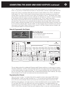
Record
OSD
Zone
NoOSDMain
Record 1 Record 2 Zone
OSD No OSD
Optical 1
Optical 3
Coax 1
Coax 2
Coax 3
Coax 4
Optical 2
Optical 4
Video 1 Video 2
Video 3 Video 4
Video 5 Video 6
Audio 1 Audio 2
Audio 3 Audio 4
Balanced Analog Audio OutputsBalanced Analog Audio Inputs
C2 Controller
Parasound Products, Inc.
San Francisco, California, USA
Input 1
Input 2
Input 3
Output
Component Video Inputs and Outputs
Sync
Red
Green
Blue
H
V
Pr Y Pb
Composite Video Inputs Video Outputs
S-Video Inputs
Video 1 Video 2 Video 3 Video 4 Video 5 Video 6
S-Video Outputs
Record
Main
Digital Out
Coax
Digital Audio Inputs
Optical
Made In
Finland
Expansion Port For
Future Technologies
IR Inputs – 12V Triggers –
RS-232 Control
External Control
L
R
L
R
Analog Audio Inputs Tape Monitor Analog Audio Outputs Programmable OutMain Analog Audio Outputs7.1 Analog Audio Inputs
1
0
AC Power
CAUTION
TO PREVENT ELECTRIC SHOCK,
DO NOT REMOVE COVER. NO USER
SERVICEABLE PARTS INSIDE,
REFER SERVICING TO QUALIFIED
SERVICE PERSONNEL.
Left
Right
Left
Right
Center
Subwoofer
Left Surround
Right Surround
Left Back
Right Back
Pro 1
Video 1
Video 2
Video 3
Video 4
Video 5
Video 6
Pro 3
Pro 1
Pro 4
Pro 2
Sub
Front Surround Center
Back
Front Surround Center
Sub
Back
Digital Out
Optical
Main Zone P1 P2 On-Off
Audio 5
Play/In Rec/Out
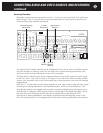
Composite
Video Outputs
S-Video
Outputs
Component
Video Outputs
AC Cord
Inlet
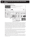
Main Viewing
Screen
Small TV
for Viewing OSD
RCA Plug
S-Video Connector
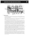
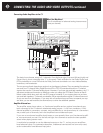
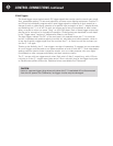
CONNECTING THE AUDIO AND VIDEO OUTPUTS continued
49
What You May Need:
•
Two composite video cables with RCA plugs
•
One S-video cable with multi-pin connectors
•
One three-cable component video cable set, with RCA
plugs at one end, RCA or BNC plugs at the other