


29
ENGLISH
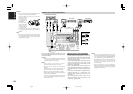
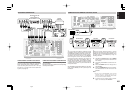
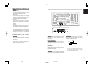
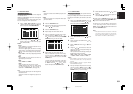
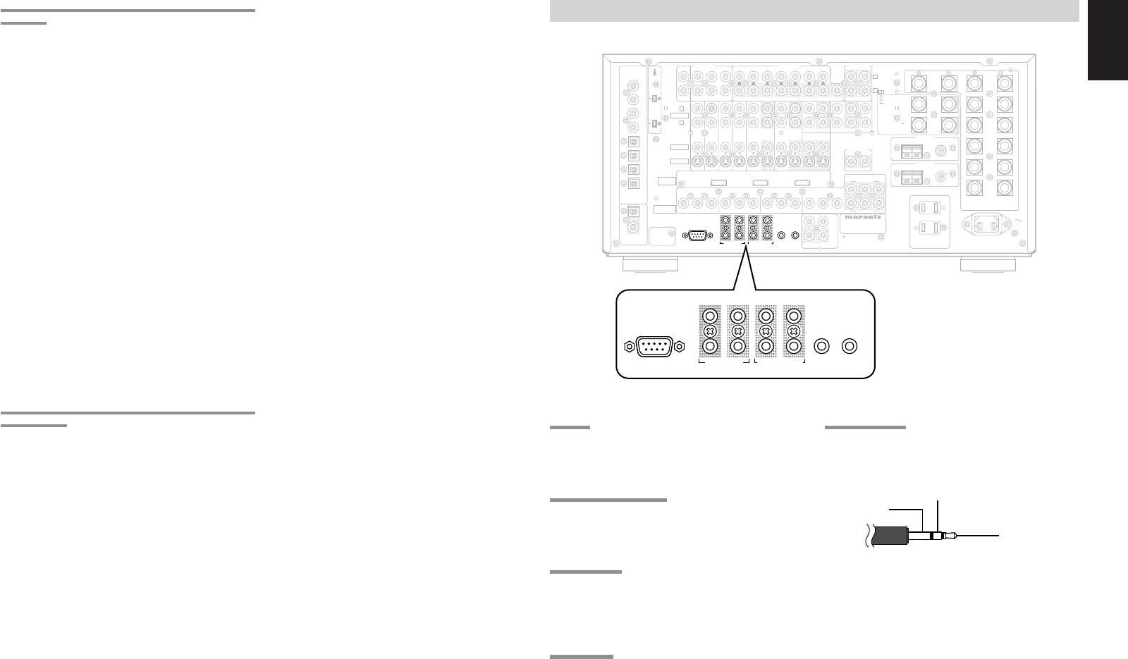
RS232C
Connect an external control device or other device
for servicing. (Use a straight cable for the
connection.)
DC OUT (DC TRIGGER)
External devices can be controlled from the
SR9600 by connecting them to the DC OUT
terminal (12 V).
EMITTER OUT
Outputs the remote control signal input to the IR
RECEIVER IN terminals. External components
can be controlled by connecting them to the
EMITTER OUT terminal.
FLASHER IN
This receiver can be controlled by connecting a
control box or other control device to this receiver.
UNSWITCHED 1A 120W MAX
SWITCHED 1A 120W MAX
AC 120V 60H
Z
AC OUTLETS
USB AUDIO
OUTPUT
INPUT
-
1
(DVD)
INPUT
-
2
(
DSS
)
INPUT
-
1
(
DVD
)
INPUT
-
3
(
VCR-1
)
2
CD
INPUT
-
2
(DSS)
2
11
2
3
44
3
RS232C DC OUT
EMITTER OUT
MULTI RC
RC
-
5
MONITOR OUT
1OUTINOUTIN
DSSTVDVD LD
TAPE
VCR-1
OUTPUT-2
OUTPUT-1
IN
MAIN IN7.1CH IN
MULTI OUT
SURR.
RIGHT
SURR.
LEFT
SPEAKER SYSTEMS
FRONT A OR B, CENTER, SURR,
SURR BACK : MINIMUM 6 OHMS
FRONT A AND B : MINIMUM 8 OHMS
CENTER
FRONT B
RIGHT
FRONT B
LEFT
FRONT A
RIGHT
FRONT A
LEFT
SL SBL SL SR SBL SBR
SW
AB
SBRSR
COAX
OPT
8
7
6
2
5
4
3
1
DIGITAL
IN
DIGITAL
OUT
OUT
AC IN
C
B
/
P
B
C
R
/
P
R
Y
C
B
/
P
B
C
R
/
P
R
Y
C
B
/
P
B
C
R
/
P
R
Y
C
B
/
P
B
C
R
/
P
R
Y
C
B
/
P
B
C
R
/
P
R
Y
R
L
MODEL NO. SR9600
TUNER-1
FM(75
Ω
)GNDAM
FM(75
Ω
)GNDAM
TUNER-2
CLASS 2 WIRING
(
AUDIO
)
S400
S400
INPUT
-
4
(
VCR-2
/
DVD-R
)
VCR-2
/
DVD-R
IN
CD-R
/
MD
OUT
R
L
(
AUX 2
)
C
AUDIO
PRE OUT
LR C
AUDIO
SW
VIDEO
S-VIDEO
R
L
MULTI OUT
VIDEO
AB
COMPONENT
VIDEO
HDMI
Ver 1.1
FLASHERRECEIVER
ININ
IR
OUT
IN
SURR.BACK
/MULTI SPK.
/SPK. C
RIGHT
SURR.BACK
/MULTI SPK.
/SPK. C
LEFT
ON
OFF
SPEAKER C
2
11
2
3
44
3
RS232C DC OUT
EMITTER OUT
FLASHERRECEIVER
ININ
IR
2
11
2
3
44
3
RS232C DC OUT
EMITTER OUT
FLASHER RECEIVER
ININ
IR
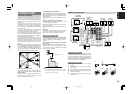
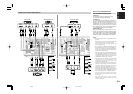
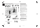
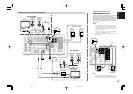
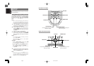
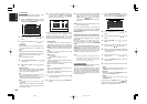
CONNECTING OTHER EQUIPMENT
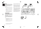
IR RECEIVER IN
This receiver can be operated by remote control
without using the internal IR receiver, by
connecting an external IR receiver.
An IR receiver is connected as shown above.
Caution:
Wrongly connecting an IR receiver or connecting
an IR receiver of the wrong voltage can damage
the SR9600, therefore do not do this.
+12V
GND
Signal
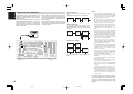
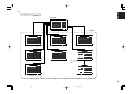
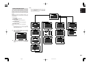
ERROR MESSAGES FOR CONNECTED i.LINK
DEVICES
“LOOP CONNECT”
This message is displayed if the i.LINK device is
connected in a loop. Connect the device so that
the connection does not form a loop.
“NODE OVER”
This message is displayed if more than 63
i.LINK devices are connected to the SR9600,
including the SR9600. Limit connections to 63 a
maximum devices including the SR9600.
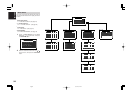
“HOP OVER”
This message is displayed if more than 17
i.LINK devices are connected in a daisy chain.
Keep daisy chain connections to a maximum 17
devices.
“BUS FULL”
This message is displayed if too many devices
are outputting signals on the i.LINK bus. Either
shut off power or disconnect unused devices.
“CANNOT LINK”
This message is displayed if the SR9600 cannot
connect to an i.LINK device or if an unconnected
device is selected as the input source.
Disconnect and reconnect the i.LINK cable, or
shut power to the SR9600 off and turn it back on.
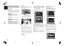
MESSAGES WHEN AN i.LINK DEVICE IS
CONNECTED
“LINK CHECK”
This message is displayed while the SR9600
checks for changes in i.LINK device
connections.
“NO SIGNAL”
This message is displayed if a signal not
supported by the SR9600 is input.
05.4.27, 5:40 PMPage 29