


22
ENGLISH
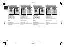
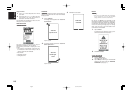
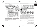
UNSWITCHED 1A 120W MAX
SWITCHED 1A 120W MAX
AC 120V 60H
Z
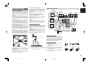
AC OUTLETS
USB AUDIO
OUTPUT
INPUT
-
1
(DVD)
INPUT
-
2
(
DSS
)
INPUT
-
1
(
DVD
)
INPUT
-
3
(
VCR-1
)
2
CD
INPUT
-
2
(DSS)
2
11
2
3
44
3
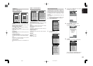
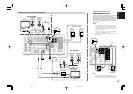
RS232C DC OUT
EMITTER OUT
MULTI RC
RC
-
5
MONITOR OUT
1OUTINOUTIN
DSSTVDVD LD
TAPE
VCR-1
OUTPUT-2
OUTPUT-1
IN
MAIN IN7.1CH IN
MULTI OUT
SURR.
RIGHT
SURR.
LEFT
SPEAKER SYSTEMS
FRONT A OR B, CENTER, SURR,
SURR BACK : MINIMUM 6 OHMS
FRONT A AND B : MINIMUM 8 OHMS
CENTER
FRONT B
RIGHT
FRONT B
LEFT
FRONT A
RIGHT
FRONT A
LEFT
SL SBL SL SR SBL SBR
SW
AB
SBRSR
COAX
OPT
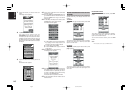
8
7
6
2
5
4
3
1
DIGITAL
IN
DIGITAL
OUT
OUT
AC IN
C
B
/
P
B
C
R
/
P
R
Y
C
B
/
P
B
C
R
/
P
R
Y
C
B
/
P
B
C
R
/
P
R
Y
C
B
/
P
B
C
R
/
P
R
Y
C
B
/
P
B
C
R
/
P
R
Y
R
L
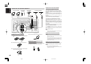
MODEL NO. SR9600
TUNER-1
FM(75
Ω
)GNDAM
FM(75
Ω
)GNDAM
TUNER-2
CLASS 2 WIRING
(
AUDIO
)
S400
S400
INPUT
-
4
(
VCR-2
/
DVD-R
)
VCR-2
/
DVD-R
IN
CD-R
/
MD
OUT
R
L
(
AUX 2
)
C
AUDIO
PRE OUT
LR C
AUDIO
SW
VIDEO
S-VIDEO
R
L
MULTI OUT
VIDEO
AB
COMPONENT
VIDEO
HDMI
Ver 1.1
FLASHERRECEIVER
ININ
IR
OUT
IN
SURR.BACK
/MULTI SPK.
/SPK. C
RIGHT
SURR.BACK
/MULTI SPK.
/SPK. C
LEFT
ON
OFF
SPEAKER C
CD
TAPEIN OUT
IN
CD-R
/
MD
OUT
OPT
5
1
DIGITAL
IN
DIGITAL
OUT
OUT IN
L
R
L
R
L R
OUT
L
R
L R
L R
L R
RL
RL RL
RL
RL
OUT IN
L
R
L
R
DIGITAL
INPUT
DIGITAL
OUTPUT
DIGITAL
OUTPUT
R LRL
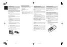
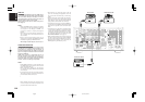
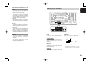
Caution:
•
Be sure to use speakers with the specified impedance
as shown on the rear panel of the SR9600.
•
To prevent damage to circuitry, do not let the bare
speaker wires touch
each other and do
not let them touch
any metal part of
the SR9600.
• Do not touch the
speaker terminals
when the power is
on. It may result in
an electric shock.
• Do not connect more than one speaker cable to
one speaker terminal. Doing so may damage
the
SR9600
.
Note:
•
Be sure to connect the positive and negative cables
for the speaker properly. If they are misconnected,
the signal phase will be reversed and the signal
quality will be corrupted.
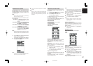
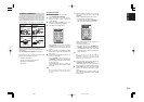
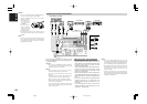
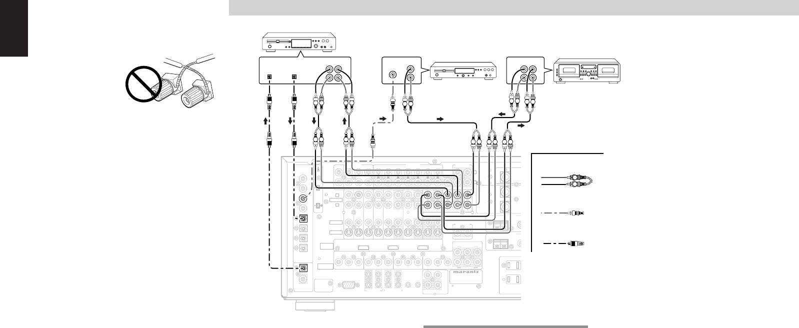
CONNECTING AUDIO COMPONENTS
The output audio signal from the TAPE OUT jack
and the CD-R/MD OUT jack is the same signal which
is currently selected.
Caution:
• Do not connect the SR9600 and other components
to a power outlet until all connections between
components have been completed.
Notes:
• Insert all plugs and connectors securely.
Incomplete connections may make noise.
• Be sure to connect the left and right channels
properly.
Red connectors are for the R (right) channel, and
white connectors are for the L (left) channel.
• Be sure to connect inputs and outputs properly.
• Refer to the instructions for each component that
is connected to the SR9600.
• Do not bind audio/video connection cables with
power cords and speaker cables. This will result in
a hum or other noise.
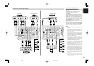
CONNECTING DIGITAL AUDIO COMPONENTS
• There are 8 digital inputs, 4 coaxial jacks and 4
optical jacks on the rear panel. You can use
these jacks to input PCM, Dolby Digital and DTS
bitstream signals from a CD, DVD, or other
digital source component.
• There is one digital output coaxial jack and one
optical output jack on the rear panel. These
jacks can be connected to CD recorder, or MD
deck inputs, respectively.
• Refer to the instructions for each component to
setup the digital audio format of a DVD player, or
other digital source connected to digital input
jacks.
• Use 75 ohm coaxial cables (for digital audio or
video) for the DIG-1, 2, 3, 4 input jacks. Use
fiberoptic cables (optical) for the DIG-5, 6, 7, 8
input jacks.
• You can designate the input for each set of
digital input/output jacks according to your
component. (see page 33)
CD RECORDER / MD DECK
CD PLAYER
TAPE DECK
ANALOG AUDIO
DIGITAL AUDIO
(COAXIAL)
DIGITAL AUDIO
(OPTICAL)
Notes:
• There is no Dolby Digital RF input jack. Use an
external RF demodulator Dolby Digital decoder
when connecting the Dolby Digital RF output jack
of the videodisc player to the digital input jack.
• The digital signal jacks on this unit conform to the
EIA standard. If you use a cable that does not
conform to this standard, this unit may not
function properly.
• Each type of audio jack works independently.
Signals input through the digital and analog jacks
are output through the corresponding digital and
analog jacks, respectively.
05.4.27, 5:40 PMPage 22