


8
ENGLISH
t
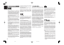
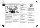
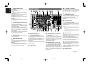
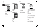
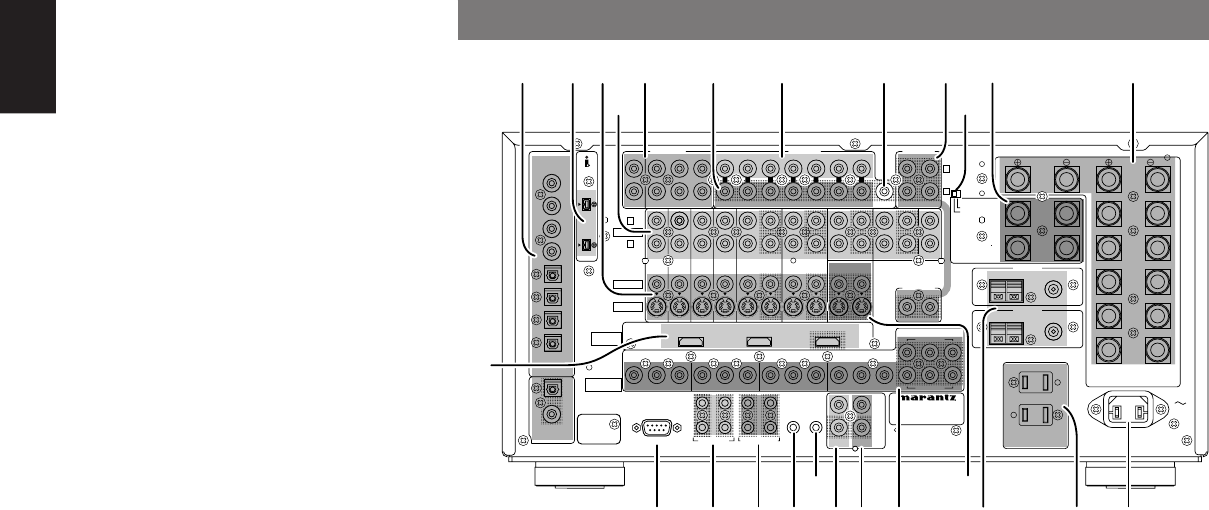
7.1 CHANNEL or AUX2 INPUT
By connecting a DVD Audio player, Super Audio
CD multichannel player, or other components that
has a multichannel port, you can play back the
audio with 5.1 channel or 7.1 channel outputs.
y
Preamp Outputs
(L, R, SL, SR, SBL, SBR, C)
Jacks for L (front left), R (front right), C (Center), SL
(surround left), SR (surround right), SBL (surround
back left) and SBR (surround back right).
Use these jacks for connecting to external power
amplifiers.
u
Main amplifier inputs
(L, R, SL, SR, SBL, SBR, C)
When the jumper plugs that link the preamp
outputs with these inputs are removed, these jacks
may be used to connect an external source to the
internal amplifiers.
Notes:
• When connecting equipment, remove the attached
jumper plugs and store them carefully so as not to
lose them.
• Only remove the jumper plugs when required.
After you finish using an main amp input jack,
replace the jumper plug.
i
Subwoofer output
Connect this jack to the line level input of a powered
subwoofer.
If an external subwoofer amplifier is used, connect
this jack to the subwoofer amplifier input.
If you are using two subwoofers, either powered or
with a 2 channel subwoofer amplifier, connect a “Y”
connector to the subwoofer output jack and run one
cable from it to each subwoofer amplifier.
o
Multiroom outputs (Audio L&R, Video)
These are the audio and video output jacks for the
multiroom A and B systems.
Connect these jacks to optional audio power
amplifiers or video display devices to listen and
view the source selected by the multiroom A and B
systems in a remote room.
!0
SPEAKER C switch
(See page 27)
e
VIDEO IN/OUT (DVD, LD, TV, DSS, VCR1,
VCR2/DVD-R)
These are the video inputs and outputs.
There are 6 video inputs, and 2 video outputs with
both composite video and S-video jack for each.
Connect VCRs, DVD players, and other video
components to the video inputs.
The 2 video output channels can be used to connect
VCRs for making recordings.
r
AUDIO IN/OUT (DVD, LD, TV, CD, DSS,
VCR1, VCR2/DVD-R, TAPE, CD-R/MD, CD)
These are the analog audio inputs and outputs.
There are 9 audio inputs (6 of which are linked to
video inputs) and 4 audio outputs (2 of which are
linked to video outputs). The audio jacks are
labeled for cassette tape decks, CD players, DVD
players, etc. The audio inputs and outputs require
RCA connectors.
q
DIGITAL INPUT (Dig. 1 - 8)/
OUTPUT (coaxial, optical)
These are the digital audio inputs and outputs.
There are 4 digital inputs with coaxial jacks, and 4
with optical jacks.
The inputs accept digital audio signals from a CD,
LD, DVD, or other digital source component.
For digital output, there is 1 coaxial output and 1
optical output.
The digital outputs can be connected to MD
recorders, CD recorders, DAT decks, or other
similar components.
w
i.LINK connector
UNSWITCHED 1A 120W MAXUNSWITCHED 1A 120W MAX
SWITCHED 1A 120W MAXSWITCHED 1A 120W MAX
AC 120V 60HAC 120V 60H
ZZ
AC OUTLETSAC OUTLETS
USB AUDIOUSB AUDIO
OUTPUTOUTPUT
INPUTINPUT
--
11
(DVD)(DVD)
INPUTINPUT
--
2 2
((
DSSDSS
))
INPUTINPUT
--
11
((
DVDDVD
))
INPUTINPUT
--
3 3
((
VCR-1VCR-1
))
22
CDCD
INPUTINPUT
--
22
(DSS)(DSS)
22
11 11
22
33
4444
33
RS232CRS232C DC OUTDC OUT
EMITTER OUTEMITTER OUT
MULTI RCMULTI RC
RCRC
--
55
MONITOR OUTMONITOR OUT
11OUTOUTININOUTOUTININ
DSSDSSTVTVDVDDVD LDLD
TAPETAPE
VCR-1VCR-1
OUTPUT-2OUTPUT-2
OUTPUT-1OUTPUT-1
ININ
MAIN INMAIN IN7.1CH IN7.1CH IN
MULTI OUTMULTI OUT
SURR.SURR.
RIGHTRIGHT
SURR.SURR.
LEFTLEFT
SPEAKER SYSTEMSSPEAKER SYSTEMS
FRONT A OR B, CENTER, SURR,FRONT A OR B, CENTER, SURR,
SURR BACKSURR BACK : MINIMUM 6 OHMS : MINIMUM 6 OHMS
FRONT A AND BFRONT A AND B : MINIMUM 8 OHMS : MINIMUM 8 OHMS
CENTERCENTER
FRONT BFRONT B
RIGHTRIGHT
FRONT BFRONT B
LEFTLEFT
FRONT AFRONT A
RIGHTRIGHT
FRONT AFRONT A
LEFTLEFT
SLSL SBLSBL SLSL SRSR SBLSBL SBRSBR
SWSW
AA BB
SBRSBRSRSR
COAXCOAX
OPTOPT
88
77
66
22
55
44
33
11
DIGITALDIGITAL
ININ
DIGITALDIGITAL
OUTOUT
OUTOUT
AC INAC IN
CC
BB
//
PP
BB
CC
RR
//
PP
RR
YY
CC
BB
//
PP
BB
CC
RR
//
PP
RR
YY
CC
BB
//
PP
BB
CC
RR
//
PP
RR
YY
CC
BB
//
PP
BB
CC
RR
//
PP
RR
YY
CC
BB
//
PP
BB
CC
RR
//
PP
RR
YY
RR
LL
MODEL NO. SR9600MODEL NO. SR9600
TUNER-1TUNER-1
FM(75FM(75
ΩΩ
))GNDGNDAMAM
FM(75FM(75
ΩΩ
))GNDGNDAMAM
TUNER-2TUNER-2
CLASS 2 WIRINGCLASS 2 WIRING
((
AUDIOAUDIO
))
S400S400
S400S400
INPUTINPUT
--
4 4
((
VCR-2VCR-2
//
DVD-RDVD-R
))
VCR-2VCR-2
//
DVD-RDVD-R
ININ
CD-RCD-R
//
MDMD
OUTOUT
RR
LL
((
AUX 2AUX 2
))
CC
AUDIOAUDIO
PRE OUTPRE OUT
LL RR CC
AUDIOAUDIO
SWSW
VIDEOVIDEO
S-VIDEOS-VIDEO
RR
LL
MULTI OUTMULTI OUT
VIDEOVIDEO
AA BB
COMPONENTCOMPONENT
VIDEOVIDEO
HDMIHDMI
Ver 1.1Ver 1.1
FLASHERFLASHER RECEIVERRECEIVER
ININININ
IRIR
OUTOUT
ININ
SURR.BACKSURR.BACK
/MULTI SPK./MULTI SPK.
/SPK. C/SPK. C
RIGHTRIGHT
SURR.BACKSURR.BACK
/MULTI SPK./MULTI SPK.
/SPK. C/SPK. C
LEFTLEFT
ONON
OFFOFF
SPEAKER CSPEAKER C
qw y o!1t u i !2e
r
!3
!7!8@2@3@4 !9@1 !4!5
@0
@5
!6
!0
REAR PANEL
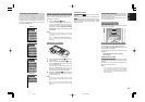
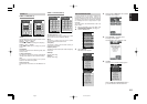
¡5
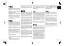
SIGNAL FORMAT indicators
2 SURROUND
This indicator is illuminated when a Dolby
Surround signal is input.
MATRIX
This indicator is illuminated when a Matrix 6.1
Surround signal is input.
DISCRETE
This indicator is illuminated when a Discrete ES +
Discrete 6.1 Surround signal is input.
DUAL MONO
This indicator is illuminated when a Dolby Digital or
DTS dual mono signal is input.
NO AUDIO
This indicator is illuminated when the input signal
is PCM NO AUDIO.
¡6
ENCODED CHANNEL STATUS indicators
These indicators display the channels that are
encoded with a digital input signal.
If the selected digital input signal is Dolby Digital
5.1 ch or DTS 5.1 ch, “L”, “C”, “R”, “SL”, “SR” and
“LFE” will be illuminated.
If the digital input signal is 2 channel PCM-audio,
“L” and “R” will be displayed. If Dolby Digital 5.1 ch
signal with a Surround EX flag or DTS-ES signal
comes in, “L”, “C”, “R”, “SL”, “S” , “SR” and “LFE”
will be illuminated.
When playing back a disk such as an SA-CD or
DVD-Audio disk, the actual audio and display may
not match with some DVD players.
¡7
VOLUME indicator
The volume level is indicated as a bar graph and
numerically in decibels.
¡8
HDMI / HDMI THR
indicator
HDMI
This indicator is illuminated when HDMI AUDIO is
set to “ENABLE” and an HDMI device is
connected to the SR9600.
HDMI THR
This indicator is illuminated when HDMI AUDIO is
set to “THROUGH” and an HDMI device is
connected to the SR9600.(See page 44)
05.4.27, 5:33 PMPage 8