


28
ENGLISH
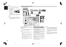
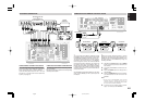
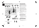
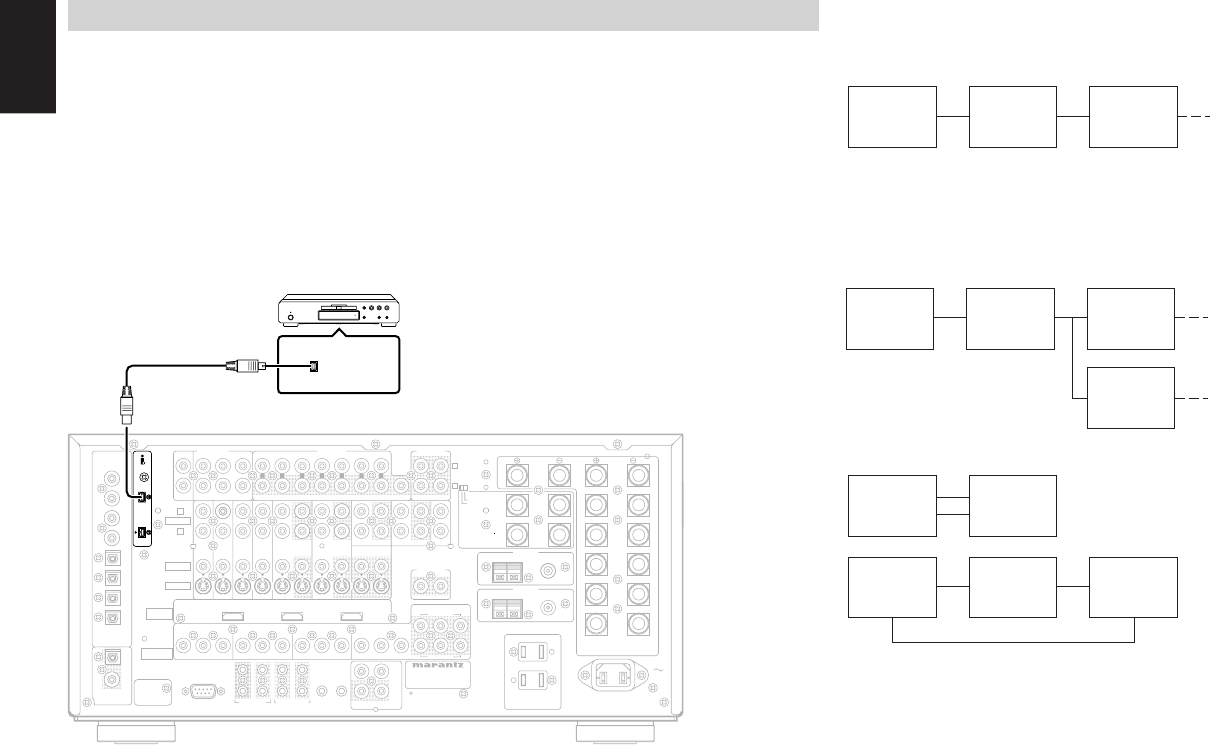
CONNECTING i.LINK COMPONENTS
The SR9600 connects to i.LINK components that
support up to S400 (400 Mbps). Use a 4-pin i.LINK
cable that supports S400 for i.LINK connections
with this receiver.
Video data cannot be transmitted via the i.LINK
(Audio) supported by this receiver. To connect to a
video component, connect the video signal
separately. When connected to other Marantz
products using i.LINK, the system can be operated
over the i.LINK cable.
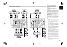
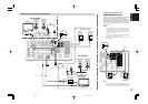
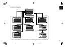
When multiple i.LINK components are connected
to the receiver, data can be transmitted through
the other i.LINK components. The components do
not have to be connected in a specific order to do
this. (see page 34)
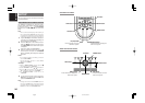
i.LINK does not distinguish between input and
output terminals in two-way communications. Input
and output are switched according to the direction
in which signals flow.
i.LINK
component
i.LINK
component
i.LINK
component
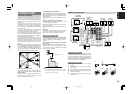
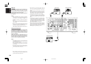
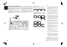
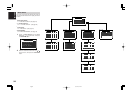
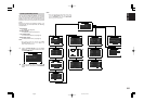
Example connection :
Up to 17 devices can be connected in a daisy
chain.
The SR9600 can detect up to 15 components.
Example connection :
Up to 63 devices can be connected in a tree
formation by branching. This kind of connection is
possible with devices that have 3 or more i.LINK
connectors.
Bad connection example:
Do not connect devices in a loop as shown in the
figure.
Notes:
• The i.LINK feature of the SR9600 supports only
devices (digital broadcast receiver (MPEG-2 TS),
digital video (DV), etc.) that support i.LINK
(Audio). Do not connect unsupported devices
because malfunctions can occur.
• During playback of an i.LINK device, do not
disconnect or connect the i.LINK cable of other
devices. Also, do not connect new devices or turn
the power on/off. This can cut off the sound.
• Some i.LINK devices cannot relay data while
power is off or the device is on standby. See the
instruction manual of the connected device.
The SR9600 does not relay data in this state
either.
• The maximum data transfer speed of an i.LINK
device is labeled near to its i.LINK connector.
This maximum data speed is standardized as S100
(100 Mbps), S200 (200 Mbps) and S400 (400
Mbps). The SR9600 has a maximum data transfer
speed of S400, but if the connected device
supports only S100 or S200, the actual data
transfer may be slower than 400 Mbps.
Mbps stands for “mega bits per second”. It
expresses the quantity of data that can be sent in 1
second. The SR9600 supports S400, therefore it
sends 400 Mb of data every second.
• The i.LINK feature does not assure the connection
and operation of all i.LINK devices. Whether data
and control signals can be exchanged between
i.LINK devices or not will depend on the
functions of each device.
• Carefully check the configuration of the i.LINK
connector before connecting an i.LINK cable.
Forcing the cable into the connector in the wrong
orientation can damage the connector.
• Do not connect an i.LINK cable with power to the
SR9600 on.
• Use an i.LINK cable that is no longer than 3.5 m
and that supports S400.
• Some players require i.LINK setup. For details,
see the instruction manual of the device.
* Some devices may require you to make settings
with the device connected to the SR9600 during
the setup.
• Audio signals input from the i.LINK connector
are not output from the DIGITAL OUT jacks.
• With some source devices, it takes time before
sound is produced. This time is needed to detect
the status of both the device and the SR9600. The
amount of time will differ according to the
connected player.
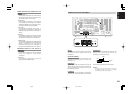
Once the devices have been connected, activate
power to the SR9600 and components, and make
the settings as explained in “i.LINK SETUP” (see
page 34). The i.LINK feature works as a temporary
input source unless the settings are made. (See
page 48)
i.LINK
component
i.LINK
component
i.LINK
component
i.LINK
component
i.LINK
component
i.LINK
component
UNSWITCHED 1A 120W MAX
SWITCHED 1A 120W MAX
AC 120V 60H
Z
AC OUTLETS
USB AUDIO
OUTPUT
INPUT
-
1
(DVD)
INPUT
-
2
(
DSS
)
INPUT
-
1
(
DVD
)
INPUT
-
3
(
VCR-1
)
2
CD
INPUT
-
2
(DSS)
2
11
2
3
44
3
RS232C DC OUT
EMITTER OUT
MULTI RC
RC
-
5
MONITOR OUT
1OUTINOUTIN
DSSTVDVD LD
TAPE
VCR-1
OUTPUT-2
OUTPUT-1
IN
MAIN IN7.1CH IN
MULTI OUT
SURR.
RIGHT
SURR.
LEFT
SPEAKER SYSTEMS
FRONT A OR B, CENTER, SURR,
SURR BACK : MINIMUM 6 OHMS
FRONT A AND B : MINIMUM 8 OHMS
CENTER
FRONT B
RIGHT
FRONT B
LEFT
FRONT A
RIGHT
FRONT A
LEFT
SL SBL SL SR SBL SBR
SW
AB
SBRSR
COAX
OPT
8
7
6
2
5
4
3
1
DIGITAL
IN
DIGITAL
OUT
OUT
AC IN
C
B
/
P
B
C
R
/
P
R
Y
C
B
/
P
B
C
R
/
P
R
Y
C
B
/
P
B
C
R
/
P
R
Y
C
B
/
P
B
C
R
/
P
R
Y
C
B
/
P
B
C
R
/
P
R
Y
R
L
MODEL NO. SR9600
TUNER-1
FM(75
Ω
)GNDAM
FM(75
Ω
)GNDAM
TUNER-2
CLASS 2 WIRING
(
AUDIO
)
S400
S400
INPUT
-
4
(
VCR-2
/
DVD-R
)
VCR-2
/
DVD-R
IN
CD-R
/
MD
OUT
R
L
(
AUX 2
)
C
AUDIO
PRE OUT
LR C
AUDIO
SW
VIDEO
S-VIDEO
R
L
MULTI OUT
VIDEO
AB
COMPONENT
VIDEO
HDMI
Ver 1.1
FLASHERRECEIVER
ININ
IR
OUT
IN
SURR.BACK
/MULTI SPK.
/SPK. C
RIGHT
SURR.BACK
/MULTI SPK.
/SPK. C
LEFT
ON
OFF
SPEAKER C
(
AUDIO
)
S400
S400
i.LINK (AUDIO)
i.LINK
component
i.LINK
component
i.LINK
component
05.4.27, 5:40 PMPage 28