


Introduction to Disk Mirroring CentreVu CMS Release 3 Version 8 Disk-Mirrored Systems
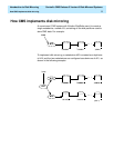
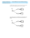
How CMS implements disk mirroring 8
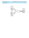
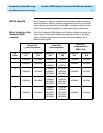
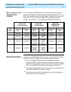
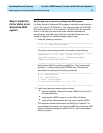
Mirror layout on a
Sun
Enterprise
3500
computer 1
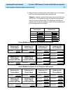
On a
Sun Enterprise
3500 platform, the mirror layout must always be
based upon the bays in which the disks are installed. Submirrors 11, 15,
and 19 are the disks in the lower bay (targets 0 through 3 on controller 0);
submirrors 12,16, and 20 are the disks in the upper bay (targets 4
through 7 on controller 1). The table below shows the mirror layout.
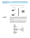
Required hardware 1
In order for your CMS system to be mirrored, it must have the following
hardware installed in addition to the hardware already installed:
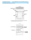
●
For a
Sun Enterprise
3500 system, two GigaByte Interface
Converter (GBIC) modules. One will be installed into the UA slot on
the FC-AL Interface board, and the other will be installed into GBIC
Port 1 on the Sbus I/O board (see the illustration on page 15).
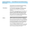
●
For a
Sun Enterprise
3500 system, a fiber cable to connect the UA
port GBIC to GBIC Port 1 on the I/O board.
●
Twice the number of disk drives needed for an unmirrored system.
All the disks must be the same size.
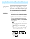
mirror d13
/
(root)
filesystem
mirror d21
/cms
filesystem
mirror d17
swap partition
(CMS r3v8)
No.
Disks
submirror
d11
submirror
d12
submirror
d19
submirror
d20
submirror
d15
submirror
d16
2 c0t0d0s0 c1t4d0s0 c0t0d0s3 c1t4d0s3 c0t0d0s4 c1t4d0s4
4 c0t0d0s0 c1t4d0s0
c0t0d0s3
c0t1d0s1
c1t4d0s3
c1t5d0s1
c0t0d0s4 c1t4d0s4
6 c0t0d0s0 c1t4d0s0
c0t0d0s3
c0t1d0s1
c0t2d0s1
c1t4d0s3
c1t5d0s1
c1t6d0s1
c0t0d0s4 c1t4d0s4
8 c0t0d0s0 c1t4d0s0
c0t0d0s3
c0t1d0s1
c0t2d0s1
c0t3d0s1
c1t4d0s3
c1t5d0s1
c1t6d0s1
c1t7d0s1
c0t0d0s4 c1t4d0s4