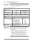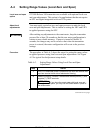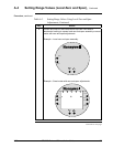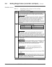
A.5 Configuring Smart Meter Using Pushbuttons, Continued
Selecting Engineering
Units
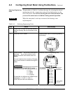
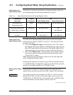
The procedure in Table A-5 outlines the steps for selecting the desired
engineering units for a smart meter using its local adjustments on the
face of the meter. You will be selecting the unit of measurement that
you want the smart meter to indicate during normal operation.
WARNING
When the transmitter’s end-cap is removed, the housing is not
explosionproof.
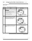
Table A-5 Selecting Engineering Units
Step Action Meter Display
1 Loosen lock on meter end-cap and unscrew
cap from housing. Be sure transmitter power
is ON.
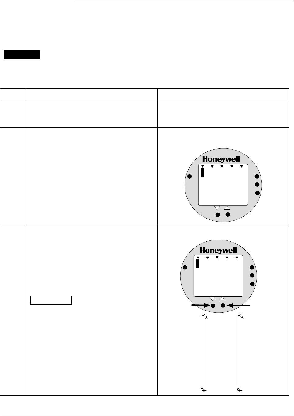
2 Press UNITS SET button. Display shows code for current engineering
units setting.
%
1000
EU
ANALOG
%
0
UPPER
VALUE
UNITS
LOWER
VALUE
SET
VAR
SEL.
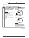
3 Press Increase key to call up next code or
Decrease key to call up previous code.
Repeat this action until desired code is on
display.
You can hold down the Increase or Decrease
key to scroll forward or backward through the
codes.
ATTENTION
Remember that if transmitter
is configured for SQUARE ROOT output
conformity the only valid code selections are
EU0 (%)
EUD (GPM)
EUE (GPH)
EUF (Custom)
If transmitter is configured for LINEAR output
conformity EU0 (%) to EUC and EUF
(CUSTOM) are valid code selections.
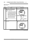
Selection codes for engineering units
%
1000
EU
ANALOG
1
UPPER
VALUE
UNITS
LOWER
VALUE
SET
VAR
SEL.
In H O
2
EU0 = %*
EU1 = inH
2
O*
EU2 = mmHg*
EU3 = PSI*
EU4 = KPa
EU5 = MPa
EU6 = mbar
EU7 = bar
EU8 = g/cm
2
EU9 = Kg/cm
2
EUA = mmH
2
O
EUB = inHg
EUC = mH
2
O
EUD = GPM*
EUE = GPH*
EUF = Custom
Press and hold to
scroll forward
through selections
Press and hold to
scroll backward
through selections
*These selections
have indicators on
the display.
Continued on next page
2/05 ST 3000 Release 300 Installation Guide
61


