


Figures and Tables
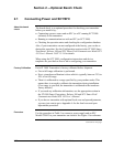
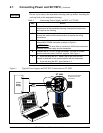
Figure 1 Typical Power Supply and SCT/SFC Connections to ST 3000. ............................................ 6
Figure 2 Location of Failsafe Direction Jumper on PWA. .................................................................. 14
Figure 3 Write Protect Jumper Location and Selections.................................................................... 15
Figure 4 Typical Mounting Area Considerations Prior to Installation ................................................. 17
Figure 5 Typical Bracket Mounted and Flange Mounted Installations ............................................... 23
Figure 6 Leveling a Model STA122 or 922 Absolute Pressure Transmitter....................................... 27
Figure 7 Typical Flange Mounted Transmitter Installation ................................................................. 29
Figure 8 Typical Flush Mounted Transmitter Installation ................................................................... 30
Figure 9 Typical Pipe and Flange Mounted Installations ...................................................................31
Figure 10 Typical Remote Diaphragm Seal Transmitter Installation.................................................... 33
Figure 11 Typical 3-Valve Manifold and Blow-Down Piping Arrangement. ......................................... 34
Figure 12 Typical Arrangement for ½” NPT Process Connection Piping............................................. 35
Figure 13 Operating Range for ST 3000 Transmitters......................................................................... 39
Figure 14 ST 3000 Transmitter Terminal Block ................................................................................... 40
Figure 15 Ground Connection for Lightning Protection........................................................................ 42
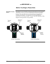
Figure A-1 Smart Meter Display with All Indicators Lit........................................................................... 52
Figure A-2 Typical Setup for Setting Range Values Using Local Zero and Span Adjustments. ........... 58
Table 1 Connecting Power Supply and SFC to ST 3000.................................................................... 6
Table 2 Testing Communications with Transmitter............................................................................. 7
Table 3 Verifying Transmitter’s Configuration Data (Using the SFC) ............................................... 10
Table 4 Cutting Failsafe Direction Jumper........................................................................................ 14
Table 5 Operating Temperature Limits (Transmitters with Silicone Fill Fluids) ................................ 18
Table 6 Transmitter Overpressure Ratings....................................................................................... 19
Table 7 Installing and Charging SFC Battery Pack........................................................................... 20
Table 8 Mounting ST 3000 Transmitter to a Bracket ........................................................................ 24
Table 9 Zero Corrects Procedure for STD110.................................................................................. 28
Table 10 Mounting Remote Diaphragm Seal Transmitter .................................................................. 32
Table 11 Suggested Transmitter Location for Given Process ............................................................ 35
Table 12 Process Connections ........................................................................................................... 36
Table 13 Flange Description ............................................................................................................... 37
Table 14 Installing Flange Adapter ..................................................................................................... 38
Table 15 Wiring the Transmitter.......................................................................................................... 41
Table A-1 Smart Meter PushbuttonDescription .................................................................................... 52
Table A-2 Smart Meter Specifications. ................................................................................................. 53
Table A-3 Setting Range Values Using Local Zero and Span Adjustments ........................................ 54
Table A-4 Smart Meter Engineering Units Code .................................................................................. 60
Table A-5 Selecting Engineering Units................................................................................................. 61
Table A-6 Smart Meter Restrictions for Setting Display Values ........................................................... 63
Table A-7 Setting Lower Display Values for Smart Meter Display ....................................................... 64
Table A-8 Setting Upper Display Value for Smart Meter Display ......................................................... 68
Table A-9 Setting Up Smart Meter Configuration Using an SFC ......................................................... 74
Table A-10 Summary of Typical Smart Meter Indications. ..................................................................... 80
Table A-11 Smart Meter Error Codes and Descriptions......................................................................... 81
Table B-1 Factory Mutual (FM) Approval.............................................................................................. 87
Table B-2 Canadian Standards Association (CSA) .............................................................................. 88
Table B-3 CENELEC / LCIE Certification ............................................................................................. 91
Table B-4 Standards Australia (LOSC) Certification ............................................................................ 92
Table B-5 Zone 2 (Europe) Declaration of Conformity ......................................................................... 92
Table B-6 NEMA Enclosure Type Numbers and Comparable IEC Enclosure Classification............... 94
vi ST 3000 Release 300 Installation Guide 2/05