


4 of 4 34-ST-99-25 (Addendum to 33-ST-33-39) 10/04
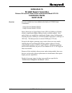
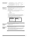
Dimension Drawings
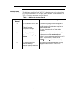
The following table provides references to dimension drawings for newly designed
ST 3000 Pressure Transmitters (Revision S and greater). If you need a copy of a
drawing, please determine the appropriate drawing number from the following table
and contact your Honeywell representative.
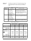
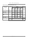
Table 2 Dimension Drawings for Transmitter Models STD110, STD120, STD125, STD130, STD170, STD924,
STD930 (Revision S or Greater)
Angle Bracket Flat Bracket Equipped with
A-G manifold part #
Vertical Pipe Horizontal Pipe Vertical Pipe Horizontal Pipe
(none)
51452896 51452895 51452894 51452893
M4AV1 51452886 51452888 51452890 51452892
M4TV1 51452885 51452887 51452889 51452891
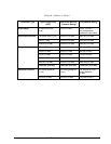
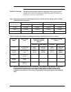
Table 3 Pressure Specification and Ratings Summary Comparisons
(Revision S or Greater)
Maximum Allowable
Working Pressure
(Note 1)
Overpressure Rating
(Note 1)
Transmitter
Model
Upper Range
Limit
Previous New Design Previous New Design
STD110 10 inches H2O
(25 mbar)
50 psi
(3.5 bar)
(Same as
previous)
50 psi
(3.5 bar)
(Same as
previous)
STD120,
STD924
400 inches H2O
(1 bar)
3000 psi
(207 bar)
4500 psi
(310 bar)
3000 psi
(207 bar)
4500 psi
(310 bar)
STD125 600 inches H2O
(1.5 bar)
" " " "
STD130,
STD930
100 psi
(7 bar)
"
"
"
"
STD170 3000 psi
(207 bar)
"
"
'"
"
Note 1 Maximum Allowable Working Pressure and Overpressure Rating vary with materials of construction;
for more specific information refer to the appropriate Specification and Model Selection Guide.
Transmitters with Graphite Gaskets have a 3625 psi rating (250 bar) except for the Draft Range
Transmitter which maintains a 50 psi rating. Flange Adapters with Graphite Gaskets have a 3000 psi
rating.