


4.2 Piping ST 3000 Transmitter
Summary
The actual piping arrangement will vary depending upon the process
measurement requirements and the transmitter model. Except for
flanged and remote diaphragm seal connections, process connections are
made to ¼ inch or ½ inch NPT female connections in the process head
of the transmitter’s meter body. For example, a differential pressure
transmitter comes with double ended process heads with ¼ inch NPT
connections but they can be modified to accept ½ inch NPT through
optional flange adapters. Some gauge pressure transmitters may have a
½ inch NPT connection which mounts directly to a process pipe.
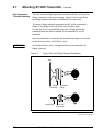
The most common type of pipe used is ½ inch schedule 80 steel pipe.
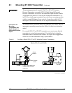
Many piping arrangements use a three-valve manifold to connect the
process piping to the transmitter. A manifold makes it easy to install
and remove or rezero a transmitter without interrupting the process. It
also accommodates the installation of blow-down valves to clear debris
from pressure lines to the transmitter.
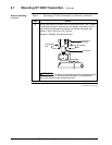
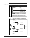
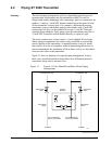
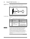
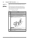
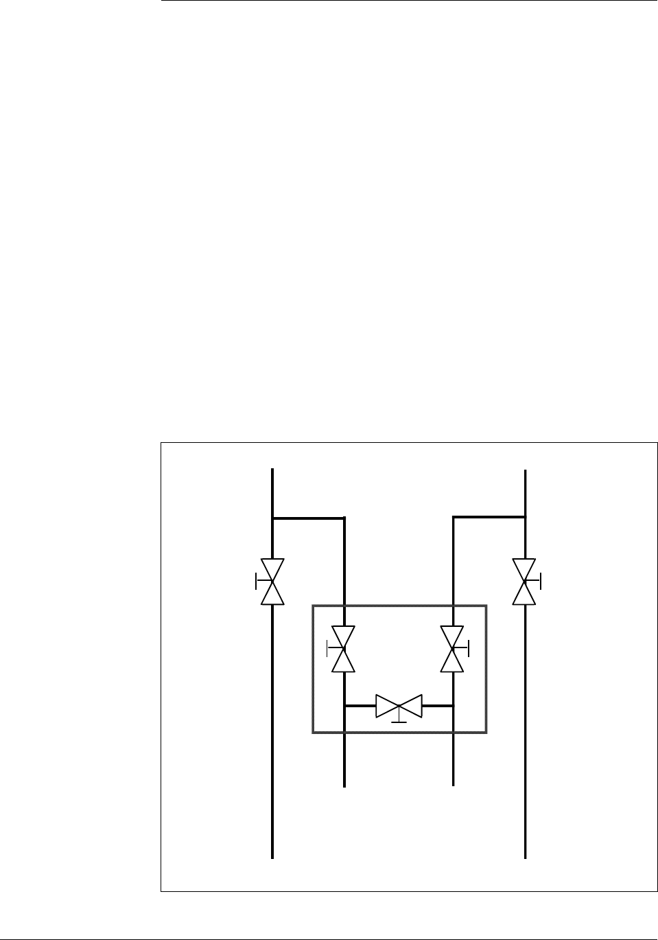
Figure 11 shows a diagram of a typical piping arrangement using a
three-valve manifold and blow-down lines for a differential pressure
transmitter being used to measure flow.
Figure 11 Typical 3-Valve Manifold and Blow-Down Piping
Arrangement.
Blow-Down
Valve
3-Valve
Manifold
To Upstream TapTo Downstream Tap
To Low Pressure
Side of Transmitter
To High Pressure
Side of Transmitter
Blow-Down
Valve
Blow-Down
Piping
To WasteTo Waste
Blow-Down
Piping
21010
Continued on next page
34 ST 3000 Release 300 Installation Guide 2/05